Figure 2-11 – Controlled Products Systems Group SWINGSMART DC 20 User Manual
Page 52
Important Considerations for DC-powered Operators
2-14
SwingSmart DC Installation and Reference Manual
Revision E
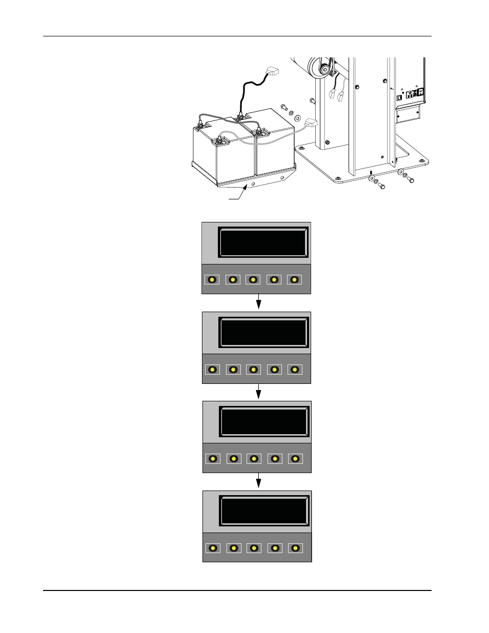
7. Place the 50Ah battery tray
between the chassis posts and
secure it using the four fasteners
provided in the kit. See
Figure 2-11.
8. Situate the two 50Ah batteries
on the tray.
9. Attach the blue wire from the
red terminal on one 50Ah
battery to the black terminal on
other 50Ah battery.
10. Run the 8Ah wire harness
through hole in the 8Ah battery
support tray.
11. Using the wires attached in the
50Ah battery kit, attach the red
wire to the red positive terminal
on the 50Ah battery. Connect
its opposite end to the red lead
exiting the support tray.
Connect the black wire to the
black negative terminal on the
50Ah battery. Connect its
opposite end to the black lead
exiting the support tray.
12. Access the Installer Menu on the
Smart DC Controller.
13. Change the Battery Setting (BT)
in the Installer Menu to a
number 1 (Extended). Follow
the steps in the menu tree
shown here.
Black
Blue
Red
Figure 2-11.
50Ah
Battery
Accessory tray
BT 1 (EXTENDED)
BATTERY TYPE
OPEN
CLOSE
STOP
MENU
RESET
PREV
NEXT
SELECT
HYSECURITY
GATE CLOSED
OPEN
CLOSE
STOP
MENU
RESET
PREV
NEXT
SELECT
CT 0 (OFF)
CLOSE TIMER
OPEN
CLOSE
STOP
MENU
RESET
PREV
NEXT
SELECT
UC 2
USAGE CLASS
OPEN
CLOSE
STOP
MENU
RESET
PREV
NEXT
SELECT
1. S.T.A.R.T. at a gate
status display.
2. Access the User
Menu, by pressing
MENU twice.
3. Access the Installer
Menu, by
simultaneously
pressing OPEN and
RESET. Release the
buttons.
4. Use NEXT to
navigate to the menu
display. Change the
setting using the
SELECT and NEXT
buttons.