Ounting, Perator, Mounting the operator – Controlled Products Systems Group SWINGSMART DC 20 User Manual
Page 28
Mounting the Operator
1-6
SwingSmart DC Installation and Reference Manual
Revision E
M
OUNTING
THE
O
PERATOR
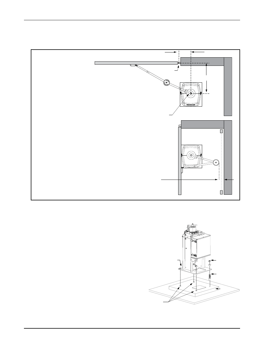
Figure 1-5.
Install the operator, by taking the following steps:
1. Assess any limitations in the surrounding area such as
curbs, walls, or bushes.
2. Before placing the operator on the pad, measure and
mark the output shaft center on the concrete pad by
selecting the X and Y dimensions. Refer to Figure 1-3
and Figure 1-5.
3. Set the operator base on the concrete pad and use it as a
template. Position the operator base so the center mark
on the pad aligns with the small hole in the base plate.
Mark the fastener and conduit cutouts. Remove the
operator from the concrete pad and drill the holes for
the concrete anchors.
4. Mount the operator with four ½ x 3½-inch concrete
anchors as shown in Figure 1-6.
Photo Eye
Photo Eye
For short gates up to 10 feet (3m):
If X = 10.5",
Set Y dimension at 14, 18, or 20".
(35.6, 45.7, or 50.8cm)
For medium gates up to 13 feet (3.9m):
If X = 12",
Set Y dimension at 22, 24, or 28".
(55.9, 61, or 71cm)
For long gates up to 20 feet (6.1m):
If X = 15",
Set Y dimension at 30, 35, or 40".
(76, 89, or 102cm)
Hinge Center
Output Shaft Center
X
Y
Potential entrapment area.
Minimum 16
"
(40.6cm) clearance
required. If less than 16
"
, install a
photo-eye or edge sensor.
Figure 1-6.
Concrete
anchor
Fasteners
Concrete
anchors
Base plate
Concrete
pad