Adjusting the limit switches -11, Adjusting the limit switches – Controlled Products Systems Group SWINGSMART DC 20 User Manual
Page 33
Gate Bracket and Linkage Arms
Revision E
Installation
1-11
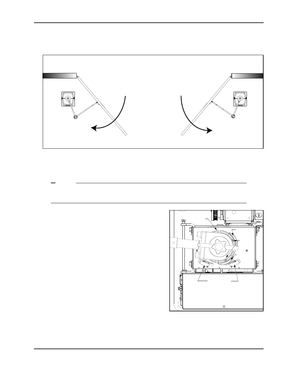
Adjusting the Limit Switches
Figure 1-12.
1. Determine whether the gate operator is a right-hand operator or left-hand operator. See Figure 1-12. Stand
on the secure side of the gate. If the gate opens to the right, it is a right-hand operator.
NOTE
For a right-hand operator, the OPEN switch is the left limit switch as shown in Figure 1-13
The opposite occurs in a left-hand operator; the OPEN switch becomes the right limit switch.
2. To adjust the limit cams, use a Phillips-head screwdriver
and loosen the fastener that secures each limit cam to the
limit plate.
3. Manually, open and close the gate. Move the limit cams
so they trip the appropriate limit switch at the full OPEN
and full CLOSE positions.
4. Secure the limit cams by retightening the two Phillips-
head screws.
A fin on the limit plate fits into the taper clamp. This feature
ensures the limits always track the gate arm position even if
the gate is struck and the taper clamp slips.
Note:When reassembling the taper clamp, make sure the limit
plate fin is seated into the slot on the taper clamp.
Left hand OPEN
Right hand OPEN
PUBLIC SIDE
SECURE SIDE
Limit switches
Figure 1-13.
Loosen
screws
Limit plate
Limit cam
Limit cam