Controlled Products Systems Group SWINGSMART DC 20 User Manual
Page 106
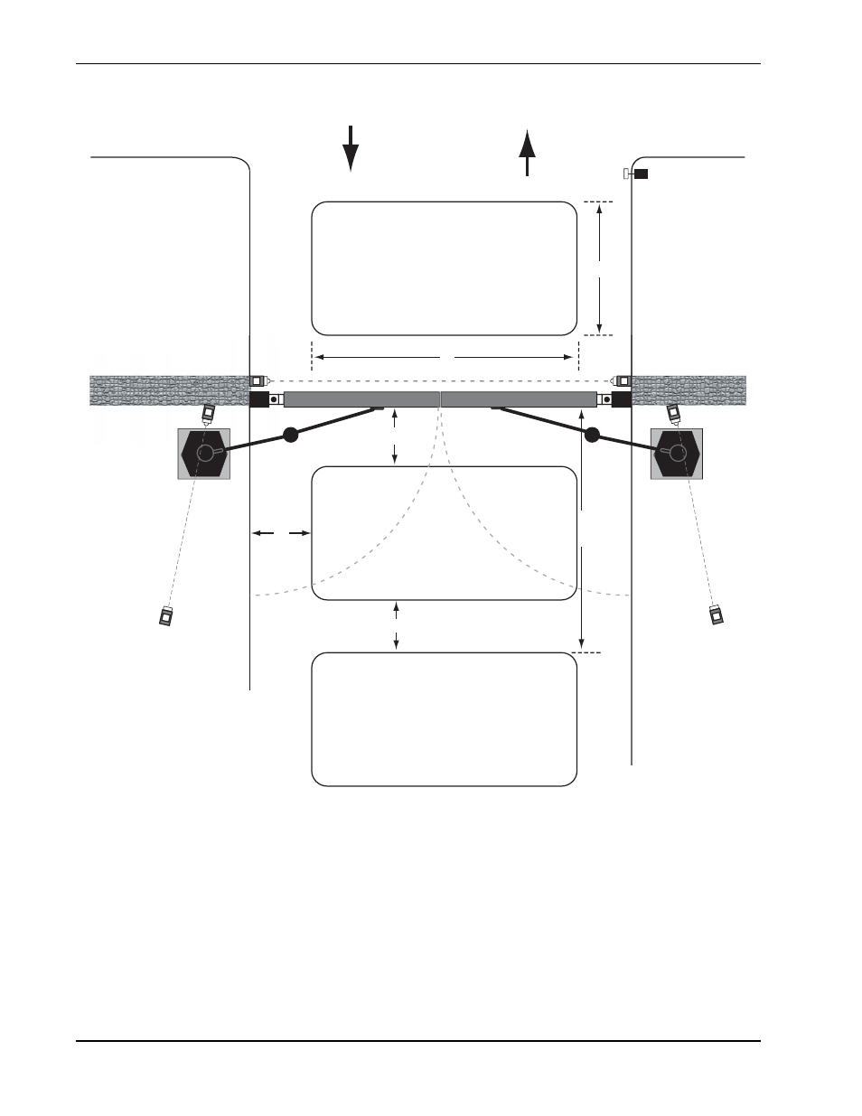
Installing Vehicle Detectors and Loops
6-8
SwingSmart DC Installation and Reference Manual
Revision E
Figure 6-7.
B
ENTER
EXIT
OBSTRUCTION
LOOP
A
ACCESS CONTROL DEVICE
(Card reader, etc.)
Vehicle Detectors and Loop Layout for Openings less than 28 feet*
PUBLIC SIDE
This layout illustrates a
bi-direcƟonal traffic system with
controlled access entry (card
reader, radio control, etc.) and a
free exit gate. The gate is closed
by a TIMER TO CLOSE. The Ɵming
to close starts when all loops are
clear. The Ɵmer is adjustable
from 1 to 99 seconds.
For a single-direcƟonal system,
the FREE EXIT loop is replaced by
an OBSTRUCTION loop.
the FREE EXIT loop is replaced by
an OBSTRUCTION loop.
SECURE SIDE
C
D
E
F
CENTER
LOOP
FREE EXIT
or
OBSTRUCTION
LOOP
* NOTE: A minimum of three (3) detectors are required for this type of gate.
DIMENSIONS
A = 6 to 20 feet (2 to 6 meters)
B = 6 to 8Ō (2m to 243cm)
C = Maintain 4Ō (122cm)
D = Maintain 5Ō (152cm) between loop
and edge of roadway. No vehicle can pass
through such a small area and escape detecƟon.
E = Maximum 4Ō (122cm). Vehicle must be
able to pass from one loop to the next
without loss of detecƟon.
F = The distance from gate to FREE EXIT
LOOP is equal to the gate panel length
plus 4Ō (122cm).