Dc battery replacement -31, Dc battery replacement, Dc b – Controlled Products Systems Group SWINGSMART DC 20 User Manual
Page 129
General Maintenance
Revision E
Reference
6-31
DC B
ATTERY
R
EPLACEMENT
HySecurity provides a one year warranty from the date of shipment for the all batteries supplied with the
SwingSmart operator.
Indicators of a low battery include:
•
LOW BATTERY or DEAD BATTERY appears on the Smart DC Controller display which may or may
not be indicative of normal discharge.
•
Alert 18 CHANGE BATTERY appears on the Smart DC Controller display. The operator emits an
audible chirp every minute to indicate a problem exists.
•
AP (#) AC LOSS appears on the Smart DC Controller display. Gate operation is affected by AC power loss
depending on customer preferences and the configuration set by the installer in the AP (#) AC LOSS User
Menu.
NOTE
For detailed information about the AP AC LOSS configuration, refer to
.
Symptoms of a low battery may include:
•
Gate remains locked in the open position
•
Gate remains locked in the closed position
•
Gate opens five seconds after AC power loss and locks open
CAUTION
!
Before replacing the batteries, turn off all power switches. Use only AGM batteries as replace-
ments (part number MX002008 or equivalent). The batteries supplied in the SwingSmart oper-
ator are state-of-the-art AGM batteries. Do NOT use flooded cell batteries as damage may
occur to the unit.
The two 8Ah batteries are easily accessible at the back of the operator on a tray behind the motor.
To replace the batteries, take the following steps:
1. Turn off the DC and AC power switches.
2. Unlock side latches to remove the SwingSmart front cover.
Remove the two Phillips-head screws and the two wing nuts
that secure the rear cover. Set the covers aside.
3. Cut the two black zip ties which secure the 8Ah batteries to
the tray.
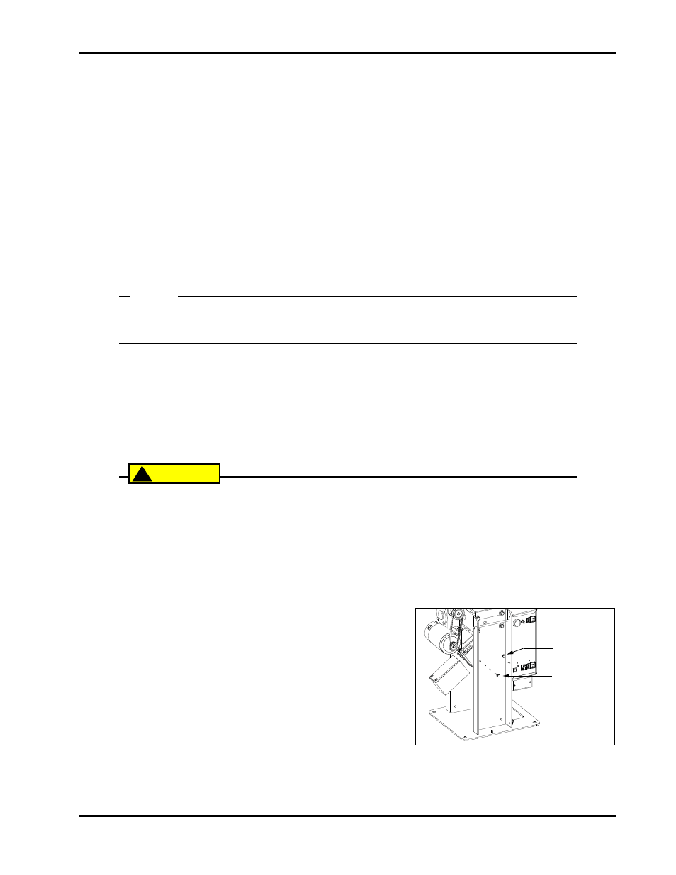
4. To disconnect the battery wires, loosen the two rear screws
and remove the front two screws that secure the support tray.
See Figure 6-17.
Figure 6-17.
Loosen rear
tray screws (2x)
Remove front
tray screws (2x)
and rotate the
tray down to
remove both
batteries.