Nstalling, Ensors – Controlled Products Systems Group SWINGSMART DC 20 User Manual
Page 112
Installing Gate Edge Sensors
6-14
SwingSmart DC Installation and Reference Manual
Revision E
I
NSTALLING
G
ATE
E
DGE
S
ENSORS
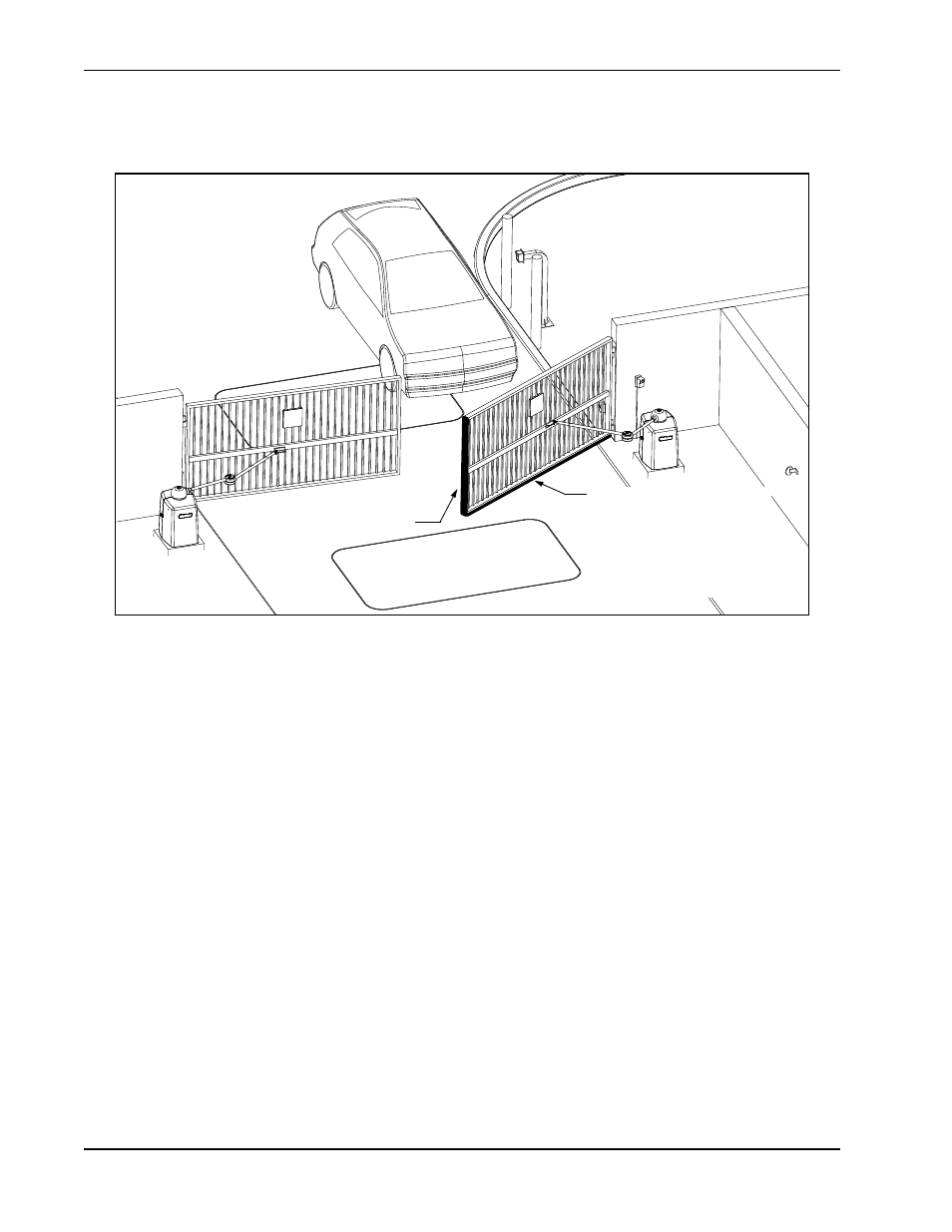
Figure 6-11.
Refer to Figure 6-11 to plan the most appropriate placement of the edge sensors being installed. For swinging
gates, one or more contact sensors (edge sensors) shall be located inside and outside the leading edge. Three-
sided detectors are ideal for swing gates. If the clearance of the gate is 6 inches (15cm) or more above the road,
then an edge sensor must be mounted on the bottom edge. Underwriters Laboratories requires that any contact
sensor used as an external entrapment protection device, must be laboratory tested to, and recognized by, the
UL 325 Standard.
Drill holes through the edge's mounting channel and through the surface that each gate edge is to be mounted.
Securely fasten every edge sensor. Make sure sensors extend to within 6 inches (15cm) of the pavement on the
leading edge of the gate.
3-sided edge sensor on the
leading edge of the gate.
3-sided edge sensor on the
bottom edge of the gate.*
*Required for UL325 compliance
if gate’s bottom edge is 6-inches
(15cm) more above ground level.