Turning both power switches on -2, Turning both power switches on – Controlled Products Systems Group SWINGSMART DC 20 User Manual
Page 54
Initial Setup
3-2
SwingSmart DC Installation and Reference Manual
Revision E
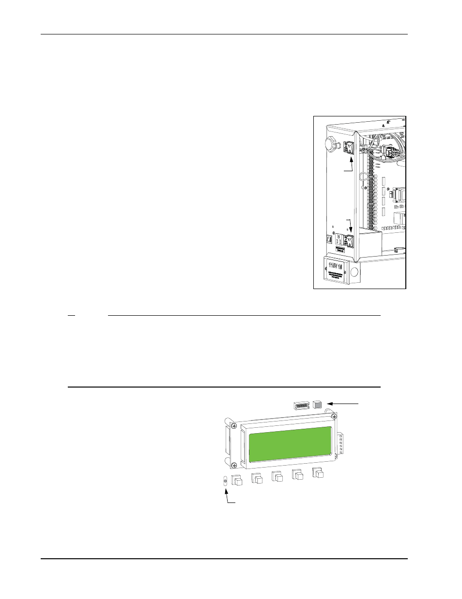
Turning Both Power Switches On
One AC and one DC rocker power switch are located on the outside edge of the control box.
Refer to Figure 3-1.
1. Turn both power switches ON. An audible beep occurs and a red light
pulsates next to the OPEN button on the Smart DC Controller which
indicates the system is functioning.
Note:If AC power is lost, the rate of flashing slows down. Other indicator
lights are described below.
2. The software version briefly appears on the LCD display and the
display settles on one of the following modes:
•
Gate status - indicates the operator is in Run Mode. Refer to
.
•
Usage class - indicates that the Setup Menu, which consists of four
sequential displays, needs to be programmed. Refer to
.
•
Error message - indicates a problem exists with the operator which
needs to be resolved before the operator can function properly.
Refer to
Smart DC Controller Troubleshooting
NOTE
The Smart DC Controller can be powered when either switch is turned on. However, the oper-
ator is a DC-powered unit and runs on its batteries. If the DC power switch is off, the operator
will not function (even though the AC power switch is on). When the operator is connected to
AC power and the unit is turned on, the charge level of the battery is being monitored and
maintained. On a solar-powered operator, the AC power switch connects and disconnects the
DC power from the solar panels.
The flashing red indicator light next to the
OPEN button on the Smart DC Controller is
considered the heart beat of the system. It
indicates that the electronics board is receiving
power. When AC power is lost, the rate of
flashing slows down. Another indicator light,
above the display, is multi-colored and
corresponds to the action that the operator is
performing:
•
Green - the operator is stopped.
•
Flashing yellow - the operator is running.
•
Red - the operator has experienced an error.
•
Not lit - AC power is lost. Pressing the SHOW LEDs button indicates which inputs, if any, are active.
Refer to Figure 4-2 for the SHOW LEDs location on the board.
Figure 3-1.
DC Power
Switch
AC Power
Switch
PREV
OPEN
NEXT
SELECT
CLOSE
STOP
MENU
RESET
Red LED flashes indicating processor
is working.
Multi-colored
LED indicates
power and gate
status.