Caution – Controlled Products Systems Group SWINGSMART DC 20 User Manual
Page 25
Pad Condition
Revision E
Installation
1-3
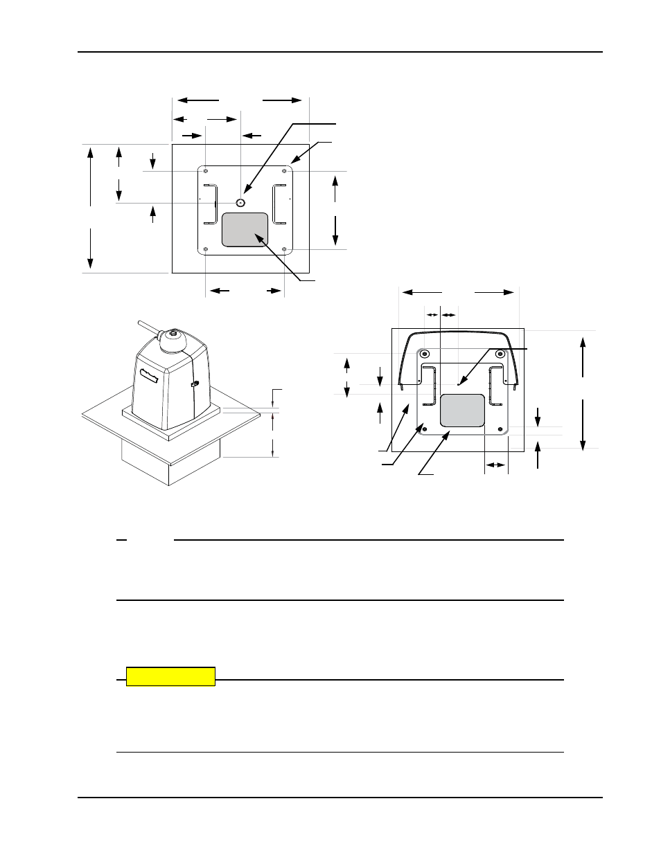
Figure 1-3.
NOTE
SwingSmart provides a 6 x 7-inch (15.2 x 17.7cm) cutout in its chassis base for conduit.
Refer to Figure 1-3. The design also provides a 9.6-inch (24.4cm) height between the control
box and chassis base for pulling and placement of wires.
3. Extend conduit height 2-inches (51mm) above the pad (4-inches/102mm above ground level). Make
sure the concrete forms are square with the gate and the pad is level. Refer to Figure 1-3 for minimum
pad dimensions.
CAUTION
Be sure to restrict conduit to the 6 x 7-inch (15.2 x 17.7cm) cutout in the chassis base if you
plan to use the extended battery backup kit. The area designed for the optional dual 50Ah bat-
teries may be obstructed if conduit is routed elsewhere. Refer to
Installing the Extended Battery
2.5"
7.6"
2.8"
1.8"
1.5"
3.5"
6" x 7"
(15.2cm x 17.7cm)
(8.9cm)
(3.8cm)
(4.6cm)
(19.3cm)
22" Cover
(56cm)
6.3cm
7.1cm
20" Cover
(50.8cm)
10.5" (26.7cm)
23" (58.4cm)
21" (53.3cm)
12" (30.5cm)
14" (35.6cm)
5.3"
5.7" (14.5cm)
minimum
10.5"
(13.4cm)
minimum
minimum
26.7cm
Pad Depth: 16" minimum
2"
m
inimum
(51mm)
(41cm)
Output Shaft Center
Drill 4 holes for ½" x 3 ½" concrete anchors
6" x 7" conduit
area
Output
Shaft
Center
Cover area
Chassis base
14.5 x 16"
36.8 x 40.6cm
Conduit
area