Controlled Products Systems Group SWINGSMART DC 20 User Manual
Page 74
Installer Menu
3-22
SwingSmart DC Installation and Reference Manual
Revision E
T
a
ble 3-2
.
Smart
DC C
o
ntr
o
ll
er - Inst
all
e
r M
e
nu
Func
ti
ons
Ref.
No.
*
In
st
aller M
enu
Set
ti
ng
Op
ti
on
s
(
Bo
ld
= Fa
ct
ory
Se
tt
ings
)
T
a
sks
an
d Ex
pla
n
a
tion
s
As
so
ciat
ed
DC Contr
o
ller
Co
nnect
io
ns
Di
splay
1
0 = G
ate
di
sabl
ed
1 =
R
esi
de
nti
al 1 to 4 u
n
it
s
2 =
Co
mm.
/p
u
b
lic access
3 =
L
igh
t indu
str
ial
4
=
Indu
str
ial
s
ecur
e
A
ssig
n
the
ope
rator
’s U
sag
e Cl
ass de
sig
n
atio
n pe
r U
L
3
25
stan
dar
d
s.
S
ee
.
Th
e in
stal
le
r
mu
st de
si
gna
te
a us
age
clas
s be
fo
re
th
e
op
er
at
or
wi
ll
fu
nc
ti
on
. Se
e
.
N
ot appl
icab
le
(N/
A
)
2
0 = G
ate
di
sabl
ed
R = R
igh
t
h
an
d
L =
L
ef
t ha
nd
Th
e h
and
ing
de
te
rm
ine
s
wh
ich
w
ay
th
e g
ate
o
p
en
s
as
yo
u
vi
ew
i
t f
ro
m
the
o
p
era
to
r s
id
e. S
ee
. Th
e in
stall
er
mu
st
d
esi
gna
te
a le
ft
or r
igh
t
ha
ndin
g be
fo
re
t
h
e op
er
at
or
wil
l f
u
n
ct
ion.
See
.
(N
/A
)
3
0 = G
ate
di
sabl
ed
1 =
0
t
o 30
0lb
s.
2
= 30
1 t
o
60
0
lb
s.
3
= 60
1 t
o
80
0
lb
s.
4
=
8
00
t
o
130
0l
bs.
Se
le
ct th
e ga
te
’s
we
ig
ht r
ang
e in
po
unds
. Th
e
in
stal
le
r
mu
st
desig
n
ate th
e g
ate
’s
w
eig
h
t
be
fo
re
th
e o
p
er
ato
r w
il
l
fu
n
cti
on
. S
ee
.
De
si
gn
ating
th
e
co
rr
ect g
ate w
ei
gh
t al
lo
w
s
th
e
op
er
ato
r
to
de
termine th
e
appro
p
ri
at
e a
cce
lera
ti
on
a
n
d dece
le
ra
ti
on
ra
tes.
(N
/A
)
4
0 = G
ate
di
sabl
ed
1 =
0 t
o 8
fe
et
2 =
8 t
o 1
2
fee
t
3 =
12
t
o 16
f
eet
4 =
16
t
o 20
f
eet
Sel
ec
t t
h
e ga
te
’s le
ng
th
i
n
f
eet
. Th
e i
n
st
al
le
r
m
u
st
d
es
igna
te
th
e
ga
te
’s l
eng
th
b
ef
or
e th
e o
p
er
ato
r w
il
l functio
n
.
See
. D
esig
n
ati
n
g th
e co
rr
ect g
ate
le
ng
th
al
lo
w
s th
e o
p
er
ato
r
to
d
etermine th
e appr
op
ri
ate
accel
eratio
n
and decel
eratio
n
r
ate
s.
(N
/A
)
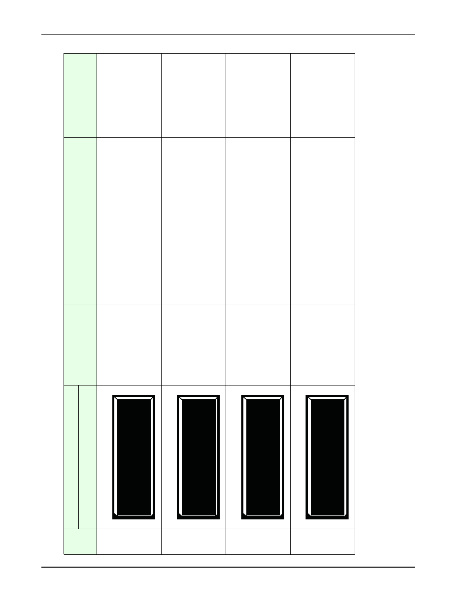
UC 0 USAGE CLASS
SH 0 GA
TE HANDING
SH 0 GA
TE HANDING
WT
0
GA
TE
WEIGHT
(LB)
SH 0 GA
TE HANDING
LN 0 GA
TE LENGTH (FT)