Onnecting, Ccessory, Evices – Controlled Products Systems Group SWINGSMART DC 20 User Manual
Page 91
Connecting Accessory Devices
Revision E
Smart DC Controller
4-9
C
ONNECTING
A
CCESSORY
D
EVICES
All accessories require a minimum of two connections on the Smart DC Controller.:
•
a device input
•
a Common Bus Terminal (COM)
Devices, such as gate edge sensors and photoelectric beams, must be installed to protect against entrapment.
These secondary entrapment protection devices are required so the gate installation is in compliance with UL
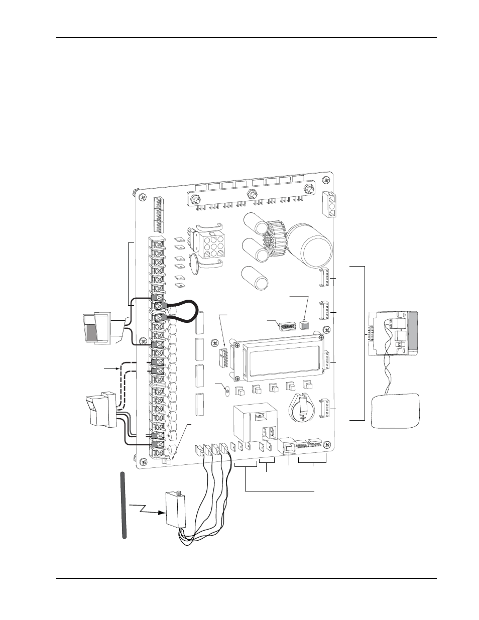
325 Safety Standards. Figure 4-5 illustrates how to connect different sensor devices to the Smart DC
Controller.
Figure 4-5. Entrapment Sensors & Accessory Connections
COM
COM
COM
COM
COM
COM
COM
COM
STOP
OPEN
RADIO
CLOSE
OPEN
OPEN
PARTIAL
EYE
OPEN
EYE
CLOSE
EXIT
LOOP
BLOCK
EXIT
IN OBS
LOOP
OUT OBS
LOOP
CENTER
LOOP
EDGE
EYE
COM
+ 24 V
EMERG
OPEN
SHOW
LEDs
RADIO OPTION
S
EDGE +24V OP
EN COM
DUAL GATE
COM
B
A
U
SER2
COM NO
DC
COMMON
TERMINALS
HY-5A
FREE EXIT
HY-5A
INSIDE LOOP
HY-5A
OUTSIDE LOOP
HY-5A
CENTER LOOP
RS-485
COMMUNICATION
USB PORT
USER RELAY 1
Electro-mechanic
al
USER RELAY 2
Solid state
24VDC
24VDC
24VAC
24VAC
12VDC
12VDC
VEHICLE LOOP
HY-5A
Access controls
Photo eye
2 channel
radio receiver
Edge
sensor
ConnecƟon for a Master/Slave gate system.
Photo eye N.O.
connects to either
EYE OPEN
or EYE CLOSE.
(Ex. Card reader, keypad)
Red LED
heart
beat
indicates
processor is
working.
MulƟ-colored LED
indicates power and gate
status.
RS232
Press buƩon to light
acƟve inputs.
RS485
ethernet
4-wire connecƟon:
+24V
EYE COM
Relay COM,
EYE OPEN or CLOSE -
(depending on funcƟon)