Setting ac power loss gate function -11, Setting ac power loss gate function – Controlled Products Systems Group SWINGSMART DC 20 User Manual
Page 63
User Menu
Revision E
Display and Menu Options
3-11
Setting AC Power Loss Gate Function
The setting in the AC LOSS display determines what action the operator performs during an AC power loss.
The settings help reduce drain on the battery. You can choose between four settings depending on customer
preferences.
NOTE
DC Solar Powered units can only be set for AP0 or AP1.
Normal gate functions continue until the system detects a battery voltage drop below 21V.
DEAD BATTERY appears on the display and the gate automatically opens. Any push-
button CLOSE command will close the gate and any open command will re-open the gate.
If the battery continues to diminish and the system detects 18V or less, the system initiates
an automatic open cycle. Any new open or close command is ignored and the LCD appears
blank. The system remains in this disabled state until reset or the battery recovers to 24V.
Normal gate functions continue until the system detects a battery voltage drop below 21V.
DEAD BATTERY appears on the display and the gate automatically closes. The gate can be
opened by a special sequence of a STOP input followed by an OPEN push-button or directly
opened with the Fire Department Open command. Any push-button CLOSE command will
close the gate. If the battery continues to diminish and the system detects 18V or less, the
system initiates an automatic open cycle if not already on a limit. Any new open or close
command is ignored and the LCD appears blank. The system remains in this disabled state
until reset or the battery recovers to 24V.
The operator automatically opens the gate five seconds after it detects an AC power loss. The
gate remains open until AC power is restored. Any push-button CLOSE command will close
the gate and any open command will open the gate. When the battery voltage drops below
21V or less, the system initiates an automatic open cycle. The gate will remain open until
the battery recovers to 24V.
The operator initially does nothing after it detects AC power loss until it receives an open
command. Once an open command is received, the operator opens and remains in that state.
Any push-button CLOSE command will close the gate and any open command will open
the gate. When the battery voltage drops below 21V or less, the system initiates an automatic
open cycle. The gate will remain open until the battery recovers to 24V.
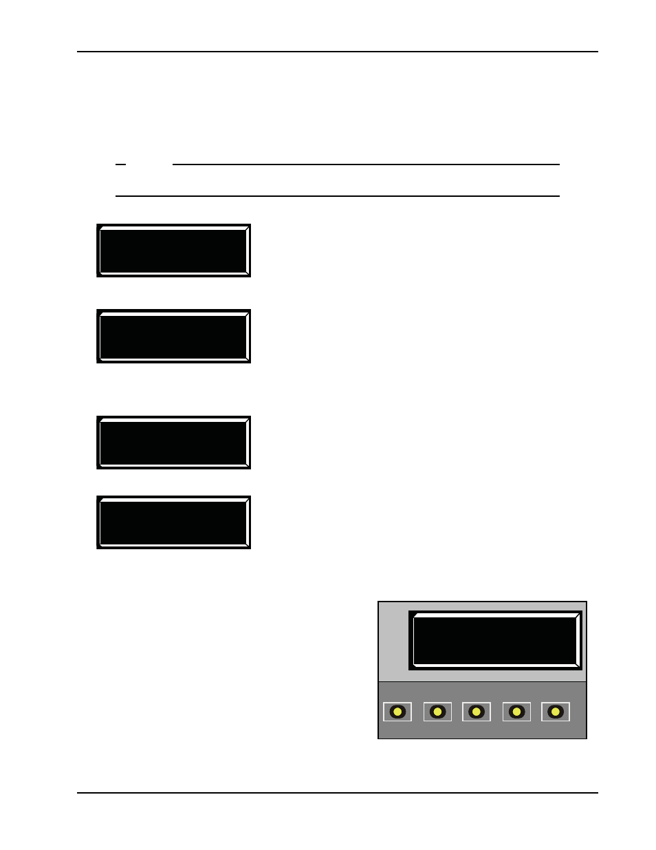
To designate what you want the operator to do during an AC power loss, take the following steps:
1. At a gate status display, press the MENU button
twice. This accesses the User Menu and the CLOSE
TIMER display appears.
2. Press NEXT until the AC LOSS display appears.
3. Use the SELECT and NEXT buttons to navigate and
change the number on the display. Review
Smart DC Controller Buttons In Menu Mode
.
4. To exit the User Menu, press the MENU button. A
gate status appears in the display indicating you have
returned to Run Mode.
AP 0 AC LOSS
UPS FAIL OPEN
AP 1 AC LOSS
UPS FAIL CLOSE
AP 2 AC LOSS
AUTO OPEN
AP 3 AC LOSS
NO CLOSE TIMER
AP 0 (AC LOSS)
UPS FAIL OPEN
OPEN
CLOSE
STOP
MENU
RESET
PREV
NEXT
SELECT