Controlled Products Systems Group SWINGSMART DC 20 User Manual
Page 82
Installer Menu
3-30
SwingSmart DC Installation and Reference Manual
Revision E
32
0 = R
u
n
m
o
de
1
=
Sh
ow
f
re
que
nc
y
2
=
Sh
ow
c
all
le
ve
l 0
-7
3
=
Se
t F
re
que
nc
y
C
on
tr
ol
s the
H
Y
-5
A F
ree
Ex
it
d
ete
ctor
.
H
Y-
5A
33
0 = R
u
n
m
o
de
1
=
Sh
ow
f
re
que
nc
y
2
=
Sh
ow
c
all
le
ve
l 0
-7
3
=
Se
t F
re
que
nc
y
Con
tr
ols th
e HY
-5A
I
n
si
de
Ob
stru
ction
L
oo
p
de
te
ctor
.
H
Y-
5
A
34
0 = R
u
n
m
o
de
1
=
Sh
ow
f
re
que
nc
y
2
=
Sh
ow
c
all
le
ve
l 0
-7
3
=
Se
t F
re
que
nc
y
Co
n
tr
ol
s th
e HY
-5
A O
u
tsid
e O
bs
tructi
on L
oo
p
dete
cto
r.
H
Y-
5
A
35
0 = R
u
n
m
o
de
1
=
Sh
ow
f
re
que
nc
y
2
=
Sh
ow
c
all
le
ve
l 0
-7
3
=
Se
t f
re
qu
enc
y
Con
tr
ol
s th
e HY
-5A
Ce
n
te
r Lo
op (S
h
adow) de
te
ct
or
.
H
Y-
5
A
T
a
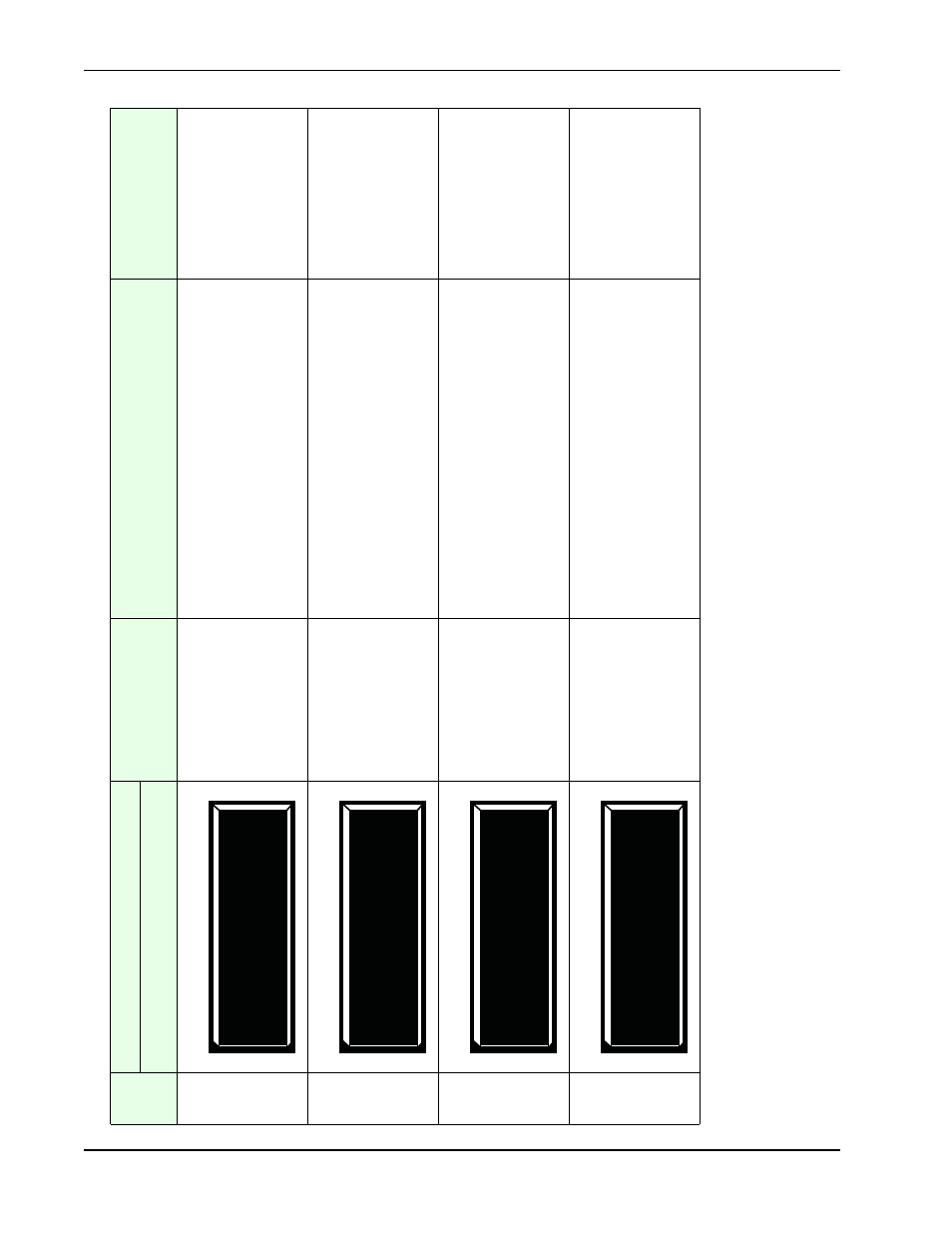
bl
e 3-2.
Smart
DC
Cont
rol
le
r - Inst
al
le
r M
e
nu
Funct
ion
s
(C
onti
nued)
Ref.
No.
*
In
st
aller M
enu
Set
ti
ng
Op
ti
on
s
(
Bo
ld
= Fa
ct
ory
Se
tt
ings
)
T
a
sks
an
d Ex
pla
n
a
tion
s
As
so
ciat
ed
DC Contr
o
ller
Co
nnect
io
ns
Di
splay
ELD 0 (RUN MODE) EXIT
LOOP
SET
ILD 0 (RUN MODE) IN OBS LOOP
SET
OLD 0 (RUN MODE) OUT
OBS LOOP
SET
CLD 0 (RUN MODE) CENTER LOOP
SET