User relays - programming procedure -11, User relays - programming procedure – Controlled Products Systems Group SWINGSMART DC 20 User Manual
Page 93
Connecting Accessory Devices
Revision E
Smart DC Controller
4-11
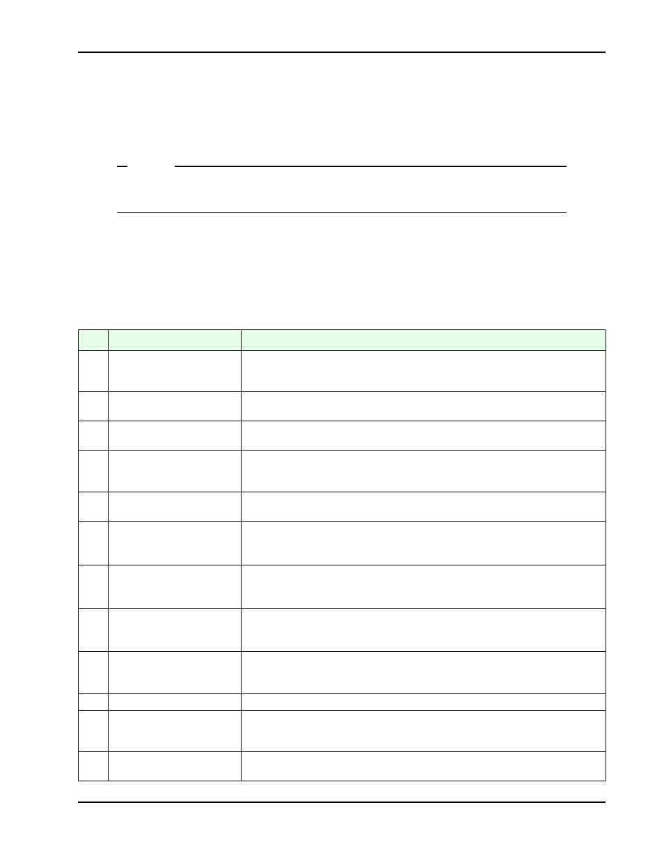
User Relays - Programming Procedure
The Smart DC Controller is able to interface with many types of external devices through the use of two user-
programmable output relays. All of the user relay functions identified and described in Table 4-3 are accessible
in the Installer Menu.
NOTE
The User Relays will operate normally to less than 18VDC. The USER 2 RELAY is rated for
DC only up to 48V and does not have an N.C. (normally closed) connection.
Use the Smart DC Controller buttons to program the user relays according to the following steps:
1. Select the relay you wish to use.
2. Enter the appropriate function using the associated number listed in the table.
Table 4-3. User-Programmable User Relays - Function Options
No.
Name
Description
1
Close limit output
Creates an interlock signal to another operator’s interlock input, or simply to indicate that the
gate is secure. The relay is released when the fully-closed limit switch is tripped. The relay is
energized when the fully-closed limit is released. (Any open command energizes the relay.)
2
Close limit pulse output
Used in a sequenced system to command a second machine to close. Generates a brief pulsed
output that occurs when the close limit is triggered.
3
Open limit output
Indicates a full-open position. This output becomes active when an open-limit is triggered
and releases when the open-limit is released.
4
Open limit pulse output
Trips a sequenced barrier arm gate operator to open. Generates a brief pulsed-output when
the open-limit is triggered. An additional pulse is also generated with any new open
command even when the gate is already fully-opened.
5
Warn before/during operate
output
Controls an external warning device. This output operates at the same time as the internal
warn before operate buzzer.
6
Gate Lock output
Controls external solenoid locks or magnetic locks. In both directions of travel, this output is
activated about 7/10
ths
of a second before the operator S.T.A.R.T.s moving the gate and
remains active while moving as well as for a few seconds after stopping.
7
Gate forced open output
Activated if the gate is forced off the closed limit switch and operator is not able to restore the
gate to full closed within four seconds. This alarm resets itself in 30 seconds.
Note: FA - FORCE OPEN ALERT must be set to 1 in the User Menu.
8
Gate open too long output
Activates when the gate is open longer than a user-selected period of time. Adjustable from 0
delay to 135 seconds delay in 15-second time increments.
Note: TL - OPEN TIME ALERT adjustments can be made in the Installer Menu.
9
Safety Mode Alert output
Activated when system is in the Safety Mode or the Entrapment Mode. Safety Mode occurs
upon an impact with an obstruction. Entrapment Mode means the gate is stopped and
occurs if the internal inherent sensor triggers while the system is in the Safety Mode.
10
Entrapment Mode Alert output
Activated only when system is in the Entrapment Mode.
11
Unauthorized Vehicle Entry
output
Activated when a second vehicle enters from the outside without a valid input from an access
control device. This output releases when an access control input signals open or the gate
reaches the close limit position.
12
Outside Obstruction Vehicle
Detector output
Interlocks an entry device to prevent pedestrian use. This output is active whenever the
Outside Obstruction Loop Detector is tripped.