Ehicle, Etector, Onfiguration – Controlled Products Systems Group SWINGSMART DC 20 User Manual
Page 90: Uick, Lose, Election
Overview of the Smart DC Controller
4-8
SwingSmart DC Installation and Reference Manual
Revision E
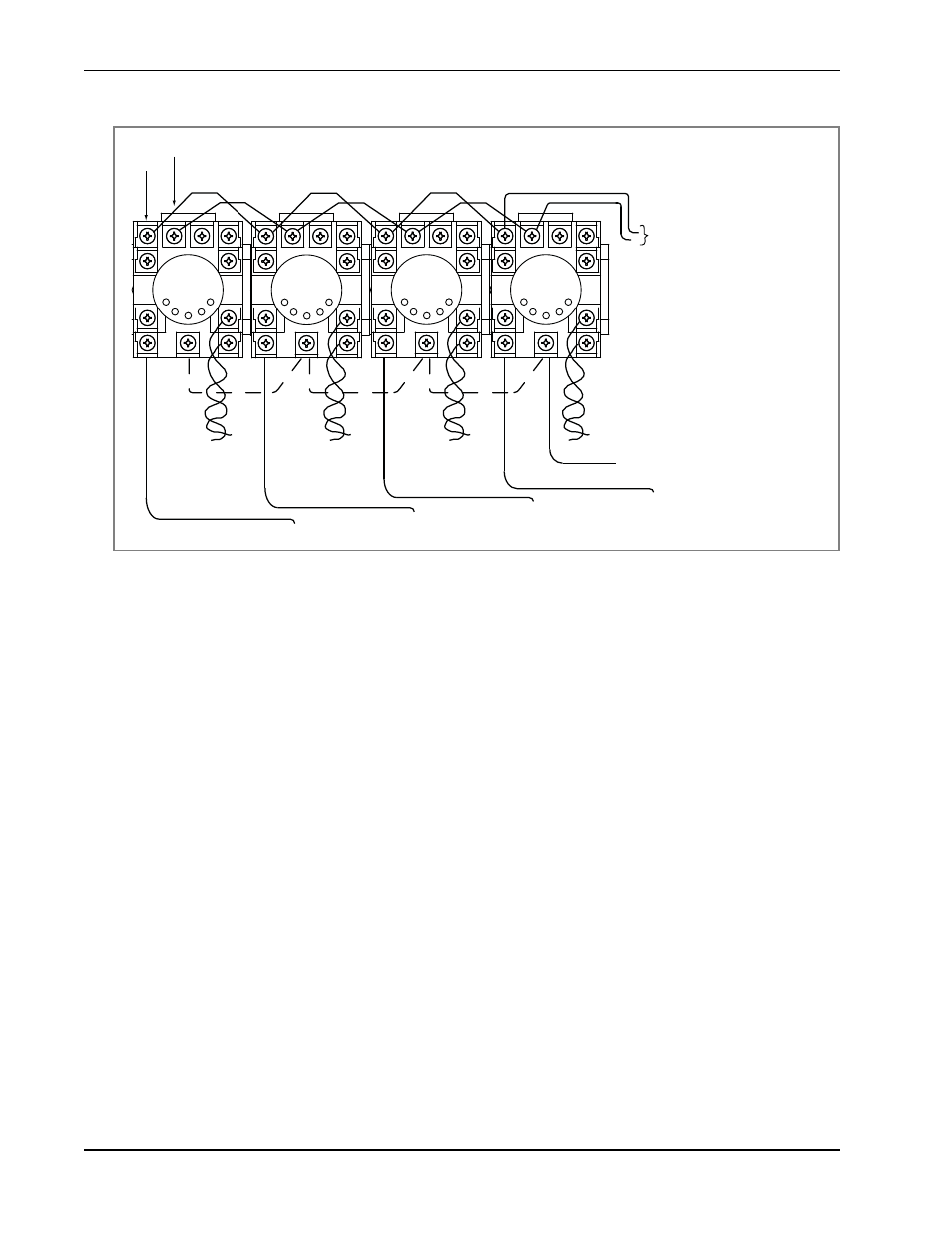
Figure 4-4. Standard 11-Pin Box Type Vehicle Detector
V
EHICLE
D
ETECTOR
C
ONFIGURATION
AND
Q
UICK
C
LOSE
M
ODE
S
ELECTION
The Standard Quick Close modes are selectable in the Installer Menu. Refer to
.
The two selectable modes are described as follows:
Mode 1 (Default)
An input from either the Free Exit, Outside Obstruction Loop, Inside Obstruction Loop or the Center
Loop will hold the gate open, reset the close timer, and block all close inputs.
Mode 2
Same function as Mode 1, except the close timer can count to zero even with the Free Exit, Outside
Obstruction Loop, Inside Obstruction Loop or the Center Loop detector inputs active. If the close timer
has counted to zero, the gate will close when all detector inputs are clear.
Inside
ObstrucƟon
Loop Detector
Outside
ObstrucƟon
Loop Detector
Free Exit
Loop Detector
Center
Loop Detector
PIN 1
PIN 2
Common
FREE EXIT LOOP terminal
IN OBS LOOP terminal
OUT OBS LOOP terminal
CENTER LOOP terminal
LOOP
LOOP
LOOP
LOOP
24VAC or 24VDC
Connect detector to match
its voltage rating