Controlled Products Systems Group 6050-080 User Manual
High voltage connection, Manual release dip-switch settings, Radio receiver loop detectors
Safety
Cover
Shadow Loop
Reverse Loop
vv
Re
Re
Rev
eee
ev
ev
eeve
e e
ssse
LL
eee L
pp
ooop
op
op
oop
Pad Base Gate
Brack
et
Post Base Gate Bracket
22”
High Voltage
Conduit
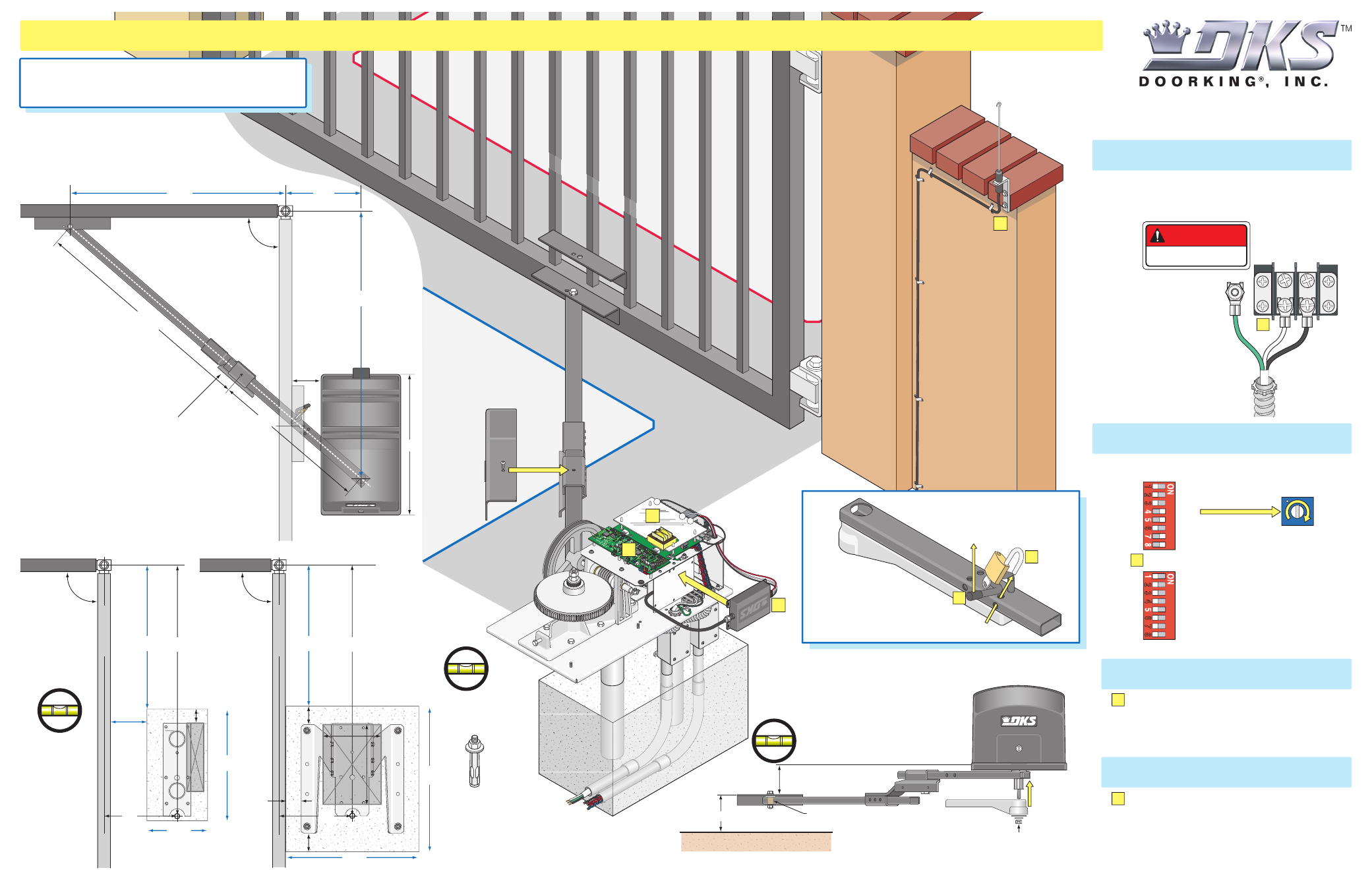
QUICKSTART “BASIC” GUIDELINES FOR STANDARD MODEL 6050/6100 - FOR GATES UP TO 10 FEET AND OPENING 90°
120 Glasgow Avenue
Inglewood, California 90301
U.S.A.
115 VAC
D
D
High Voltage Connection
Tip:
It is recommended that a surge suppressor
be installed on the high voltage power lines.
GATE OPERATOR MUST BE PROPERLY GROUNDED!!
Copyright 2013 DoorKing, Inc. All rights reserved.
6050-066-E-1-13
Important:
The elbow
assembly must be in the
correct position on the arms
BEFORE cycling operator the
first time.
A
Neutral
115 V
AC
Chassis
Ground
DANGER
HIGH VOLTAGE!
Models 6050/6100 is intended for installation
only on swing gates used for vehicles.
Pedestrians must be supplied with a separate access opening.
For safety and installation instructions, please
refer to the Installation/Owner’s manual.
A
Low
Volt
3/4” with
Sweeps
High
Volt
1. Com to #20
2. Relay to #11
3. 24
Volt
to #7
Elbow
Assembly
Elbow Flange
Loop Conduit
Flexible
Conduit
Depth
of th
e
concrete is
determined by
soil conditions
and local
building codes.
Junction Boxes
AC
Power
Condu
it
90°
Open Gate
Note: 2” thick gate Illustrated.
Note: 2” thick
gate Illustrated.
Closed Gate
23”
4”
Gate Bracket
Output
Shaft
Important:
A straight
line drawn from the
closed gate bracket
through the open
gate bracket MUST
intersect the operator
output shaft.
34”
12”
Important:
Elbow flange MUST be on
the opposite side of the closed gate.
Manually adjust the arms to get the
correct open and closed positions
BEFORE powering up the operator.
Open/Close limits will be automatically
set the first time operator is cycled.
37.5”
24”
Operator Position
Concrete Position
Arm Assembly and
Gate Bracket
Height
Post
Base
Pad
Base
Open Gate
Closed Gate
90°
90°
Run conduit on
the opposite
side of the
open gate for
the post base.
Secure operator
to the concrete
pad with four (4)
3/8” x 3” sleeve
anchors
(not supplied).
Mount the
post base into
the concrete
before
installing the
operator.
Closed Gate
2.5”
3”
3”
2”
Conduit
Right Support Le
g
Left Support Le
g
Open Gate
Bottom
Plate of 6300
Important:
Adjust the locknut on the crank power arm
so that it is snug against the washer, but will still allow
the 30” crank arm to rotate with little force.
30” Crank Arm
60” Connecting Arm
Flange
Crank Power Arm
Elbow Assembly
Brass Bushing
Gate
Bracket
Ground
Arms and Operator MUST be level.
Varies with base used.
5”
Manual Release
DIP-Switch Settings
•
NO AC power.
•
NO DC power (On select models).
Pad MUST
be Level.
Post Base
MUST be Level.
Post
Base
Concrete Pad
Concrete
1
2
Crank Power Arm
Crank Arm
3/8
Using shadow loop and gate opening in direction shown.
SW 1
1. OFF
2. OFF
3. OFF
4. ON
5. ON (Operator Type)
6. OFF
7. ON (Single Operator)
8. ON (Tamper Protect)
1. OFF (Opening Counter-Clockwise)
2. OFF
3. OFF
4. OFF
5. OFF (Normal Reverse Function)
6. OFF
7. OFF
8. OFF
SW 2
Auto Close
Timer
Adjust
1 to 23 sec.
B
Conduit
Crank Power Arm
will remain stationary
during manual gate movement.
43”
24”
24”
26”
6”
12”
43”
43”
12”
10”
18.5”
Output
Shaft
Output
Shaft
Position
14”
10”
(See reverse side)
C
Not included - Refer to the Installation/Owner’s
manual and Loop Information Manual (available
FREE from
www.dkaccess.com
) for more
information on loops and loop detectors.
Radio Receiver
Loop Detectors
D
Not included - Refer to a specific Radio Receiver
Manual (available from
www.dkaccess.com
) for
more information on radio receivers and antenna
installation. (See reverse side for wiring)
C
B
20
11
7