Setting the taper clamp -15, Setting the taper clamp – Controlled Products Systems Group SWINGSMART DC 20 User Manual
Page 37
Gate Bracket and Linkage Arms
Revision E
Installation
1-15
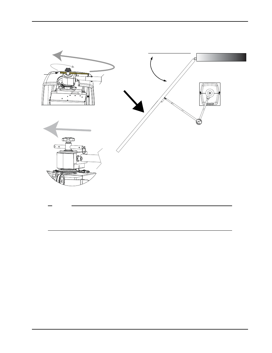
Setting the Taper Clamp
Figure 1-16.
NOTE
Setting the taper clamp with the gate closed impedes traffic flow. If vehicles need to pass
through the gate area, delay setting the taper clamp until after the operator has been configured
to run. Refer to Chapter 3,
The taper clamp is made of two pieces: a cone-shaped hub fits into a taper clamp assembly. The more you turn
the taper handle clockwise the harder it becomes to slip the clutch. In certain situations, such as secure military
facilities, consider straightening the gate arm instead of over-tightening the taper clamp. Refer to
1. To loosen and release the taper clamp, extend the taper handle and turn the handle counterclockwise. See
2. Manually, swing the gate half way between the open and closed position (approximate 45° angle).
3. To tighten the assembly, turn the taper clamp handle clockwise in 1/8-inch (3.2mm) increments. A large
amount of torque is not required in order to obtain a tight clutch setting.
4. Push the gate end with approximately 100 pounds of force to simulate a gate strike. If the taper clamp
slips, use the taper handle to further tighten the assembly.
5. Continue to adjust the taper clamp until no slippage occurs.
6. Retract and center the taper clamp handle.
Tighten
Retract
45° angle
Simulate a gate strike
with ~ 100 lbs. of
force.
Loosen
Taper
handle