Installing the linkage arms -9, Installing the linkage arms – Controlled Products Systems Group SWINGSMART DC 20 User Manual
Page 31
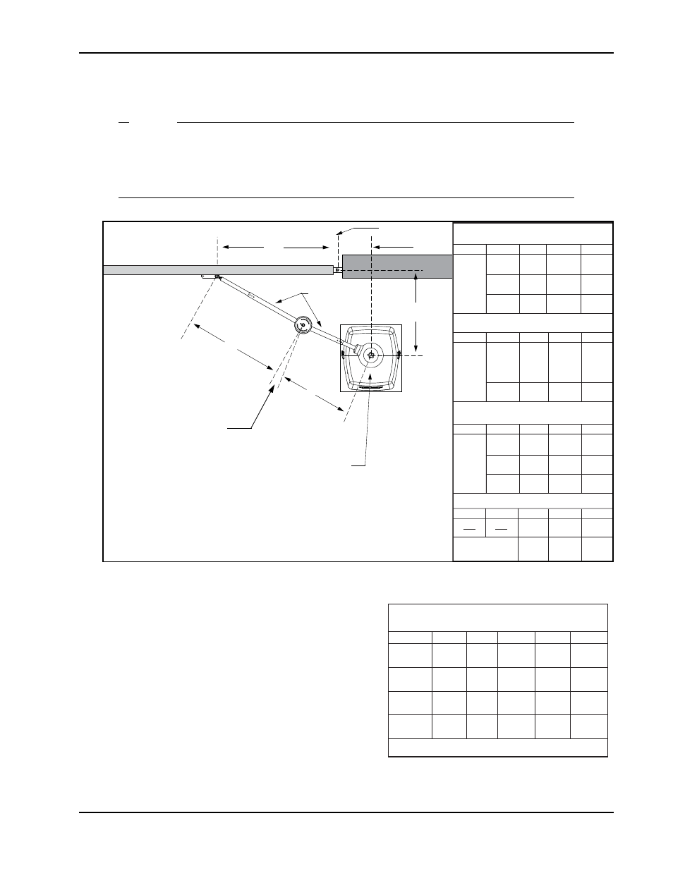
Gate Bracket and Linkage Arms
Revision E
Installation
1-9
Installing the Linkage Arms
NOTE
SwingSmart operators ship with separately packaged linkage arms. The linkage arms have a
universal elbow joint and can be used on either an operator with right handing or left-handing
by simply flipping the linkage arms. The excess on the over travel stop is then sawn off to
accommodate for the top and bottom elbow joint covers.
Figure 1-9.
1. Slide the linkage tubes on the appropriate stub arms
and use the tapped holes for adjustment purposes.
Tighten the hex-head bolts to hold the arms in place.
Refer to Figure 1-10.
2. Verify the A and B dimensions on the arm linkage
tubes. For short gate applications, the linkage arms
must be cut to achieve the required lengths. See
Figure 1-9. If your operator position does not fit the
chart specs, use the Custom Gate Installation formula
to determine the proper length.
X
Xg
Hinge Center
Y
Short Gate Installation:
For gates up to 10 feet (3 meters)
X
Y
Xg
14"
23.5"
10.5"
18"
27.5"
Medium Gate Installation:
For gates up to 13 feet (4 meters)
36cm
27cm
60cm
46cm
70cm
20"
29.5"
51cm
75cm
X
Y
Xg
22"
33"
12"
24"
35"
56cm
31cm
84cm
61cm
89cm
28"
39"
71cm
99cm
A
B
15.5"
21.5"
17.5"
24.5"
39cm
55cm
44cm
62cm
19"
26"
48cm
66cm
A
B
21"
29"
22"
30.5"
53cm
74cm
56cm
78cm
24"
33.5"
61cm
85cm
Long Gate Installation:
For gates up to 20 feet (6 meters)
Custom Gate Installation:
X
Y
Xg
X + Y - 1
X
Y
Xg
30"
44"
15"
35"
49"
76cm
38cm
112cm
89cm
124cm
40"
54"
102cm
137cm
A
B
0.87 * Xg
0.63 * Xg
A
B
28"
38.5"
30.5"
42.5"
71cm
98cm
78cm
108cm
33.5"
46.5"
85cm
118cm
Space for custom
calculations:
Operator Center
A
B
Linkage arms
NOTE: Maximum measurement for A = 38 inches (97cm)
Maximum measurement for B = 47.5 inches (121cm)
Keep the elbow joint at a slight
angle to avoid hyperextension and
allow compensation for light gate
strikes without severe damage to the
gate operator.
NOTE: At secure sites, straightening the
arm lowers the chance of someone
manually pushing the gate open.
Operator Placement & Gate Arm Geometry
for 100° through 130° opening
X
Y
Xg
24"
36"
91cm
41"
104cm
A
B
24"
61cm
36"
91cm
28"
71cm
40.5"
103cm
31.5"
80cm
44"
112cm
18"
46cm
44"
112cm
36"
91cm
47.5"
121cm
32"
81cm
38"
97cm
° of Swing
100°
110°
120°
130°
NOTE: Maximum A = 38" (97cm) Maximum B = 47.5" (121cm)
20"
51cm
26"
66cm
61cm
24"
61cm
39"
99cm
20"
51cm