CTI Products MCN Server 8000 User Manual
Page 80
MCNConfig Program:
Network Interface Window
80
68-12286-110
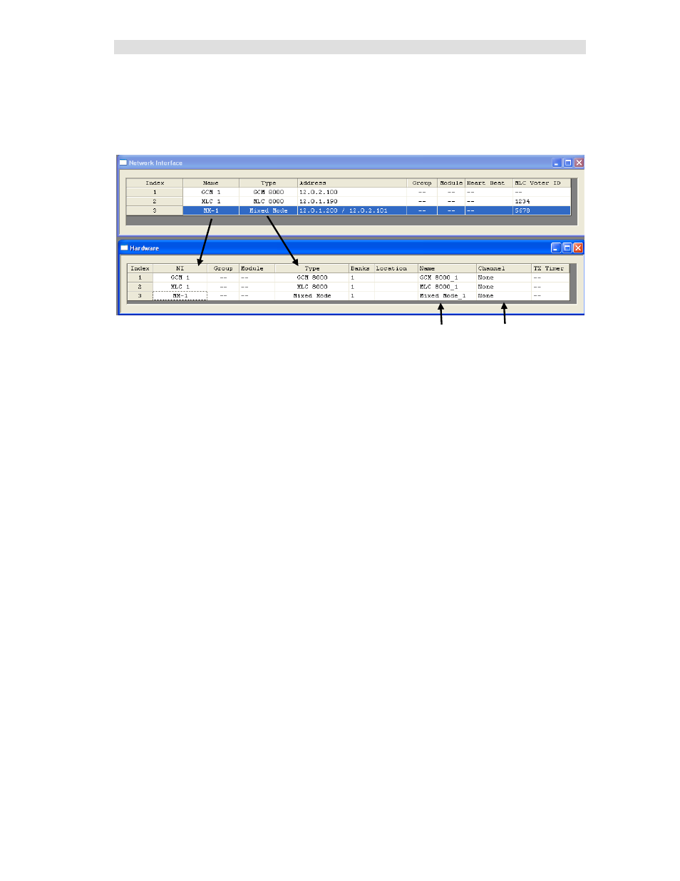
IP Comparator Representation in the NI and Hardware Windows
The configuration information for the IP comparators is displayed in the NI Network Interface window
and the Hardware window as shown below:
The NI Name and Type fields from the Network Interface window as shown by the arrows.
The above system has the following comparators defined:
•
GCM 8000 Stand-alone
•
MLC 8000 Analog Comparator Stand-alone
•
MM Mixed Mode (MLC 8000 Analog Comparator & GCM 8000
The system will be connected to (4) physical comparators:
•
(2) GCM 8000 comparators and
•
(2) MLC 8000 Analog Comparators
However, we see only (3) comparators are shown in the Hardware window:
•
Each of the stand-alone comparators has its own line.
•
The Mixed Mode system appears as one line in the hardware window.
The Mixed Mode entry in the Network Interface window ties together the two comparators used in the
Mixed Mode system (with the dual IP addresses and the MLC ID). The MCN Server 8000 software will
communicate with both in the Mixed Mode system (as defined in the Network Interface window) and
combine them as one logical Mixed Mode comparator.
Additionally, the Receivers (or BRs) for each of the comparators will be configured in the Receiver
window (see the Adding Receiver Data - Receivers Resource Window section on page 94 for details).
Each of the three comparators in the Hardware window will have 64 receiver slots assigned to it in the
Receivers window. For the Mixed Mode solution, the status data from the digital GCM 8000 and the
analog MLC 8000 Analog Comparators will be combined and directed to one receiver display for each
Receiver/BR in the Mixed Mode system.
If you don't have any HIB-IPs in your system, skip ahead to the Configuring the Hardware - Hardware
Resource Window section on page 88 .
Comparator
Name
Radio
Channel