CTI Products Quad Router Panel User Manual
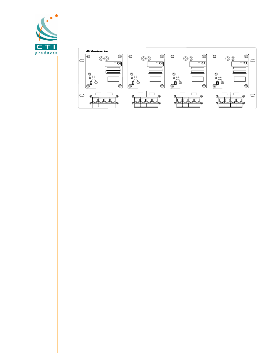
Routers for mcn ™ monitoring and control systems, Quad router panel with 4 routers installed, Introduction
Routers
for MCN
™ Monitoring and Control Systems
Introduction
Routers are used with CTI's MCN Remote
Comparator Display system for the following
purposes:
To increase the number of I/O Modules
(CIBs, AIBs, IOBs, etc.) past 16.
To establish a high-speed (1.25 Mb)
backbone network.
To provide access to a high-speed
network from a standard speed (78 Kb)
HIB module for dial-up applications.
To connect local I/O modules to a high-
speed backbone.
Mounting
A
Quad
Router
Mount
is
available
for
mounting on an EIA 19" rack. It will accept up
to 4 routers. It requires 4 RU of space (7").
An
MCN
power
supply
is
required
for
operation.
System Operation
The system diagram on the next page shows
how routers are used to extend the number of
I/O modules past 16. There are two standard
speed (78 Kb) networks segments shown,
each with 16 CIB modules.
Each of these segments is connected to the
78 Kb side of a router module.
The high-
speed (1.25 Mb) sides of the routers are
connected together to form a high-speed
backbone network.
The lower router is a HIB router, which allows
a dial-up HIB module to be used.
Although not shown in the system diagram,
PCs with high-speed PCLTA interface cards
can be connected directly to the 1.25 Mb
channel.
The traffic from the CIB modules is passed
through the router modules and onto the high -
speed backbone.
The routers filter the network traffic so that the
CIB traffic from one 78 Kb segment is not
repeated to the other 78 Kb segment. Traffic
from the User Interface (PCLTA or HIB) is
passed to the appropriate 78 Kb segment.
Dial-Up HIB Applications
Speed conversion is required when a HIB
module is used in dial-up applications that
have a high-speed backbone.
For these
applications, order one router module for each
dial-up HIB module.
The HIB Router will convert from the 1.25 Mb
high-speed network to the standard 78 Kb
network for the HIB. It also provides filtering
so that the HIB will see only a portion of the
network traffic at any one time.
Custom System Configuration
The configuration for the routers will be
different
for
each
customer's
system.
Parameters such as filtering and addressing
must be set for each of these systems.
HIB routers are pre-configured for standard
addressing.
the
MCNRCD
Comparator
Display software on the PC will automatically
set up the filtering on the HIB routers,
depending on which screens are loaded.
For
all
non-HIB
routers,
the
Custom
Configuration option must be ordered.
CTI
Products'
engineers
will
work
with
the
customer to define the network. We will then
custom configure the routers before shipment.
We will provide the appropriate files to the
customer to allow re-configuration if a router
needs to be replaced in the field.
CTI Products, Inc.
1211 West Sharon Road
Cincinnati, Ohio 45240
USA
phone
+1.513.595.5900
fax
+1.513.595.5983
IN
OUT
IN
OUT
1250
78K
B
ROUTER 2
A
IN
OUT
IN
OUT
1250
78K
B
ROUTER 1
A
IN
OUT
IN
OUT
1250
78K
B
ROUTER 3
A
IN
OUT
IN
OUT
1250
78K
B
A
ROUTER 4
QUAD ROUTER PANEL
LISTED 17BK
TP/FT-10 TP/XF1250
E NE R
GY MA N
A GE ME NT
EQ UIPMENT SUBAS
SEM BL
Y
L
U
L
U
C
EAST POL ICE
RTR1.LSC
Router #
LISTED 17BK
TP/FT-10 TP/XF1250
ENERGY MANAGEMENT
EQUIPMENT SUBASSEMBLY
L
U
L
U
C
RTR2.LSC
Router #
LISTED 17BK
TP/FT-10 TP/XF1250
ENERGY MANAGEMENT
EQUIPMENT SUBASSEMBLY
L
U
L
U
C
RTR3.LSC
Router #
9819
LISTED 17BK
TP/FT-10 TP/XF1250
ENERGY MANAGEMENT
EQUIPMENT SUBASSEMBLY
L
U
L
U
C
ID 000203580900
ID 000203625900
RTR4.LSC
Router #
RTR1.LSC
To RTR
Rack 1
Term
From RTR
To RTR
Term
From RTR
To RTR
Term
From RTR
Term
RTR2.LSC
Rack 2
Rack 3
RTR3.LSC
Rack 4
RTR4.LSC
CA-80465-101
WEST POLICE
NORTH POLICE
SOUTH POLICE
CIB 10-0
#2
1250
#1
#3
CIB 20-0
Network
#2
#4
CIB 30-0
CIB 40-0
#3
Term
To 1250
A
B
A
B
A
B
B
A
B
A
B
A
B A
B A
Quad Router Panel with 4 Routers Installed