Table 24 shunt type configuration – GE Industrial Solutions Pulsar Plus Controller User Manual
Page 79
Pulsar Plus Controller Family
Issue 7 December 2011
79
Table 23 Shunt Monitors Configuration
Defaults
The controller is factory configured with:
ID1
Type: Battery
Shunt: 300A
ID2
Type: None
Shunt: 300A
ID3
Type: None
Shunt: 600A
ID4
Type: None
Shunt: 600A
ID5
Type: None
Shunt: 600A
ID6
Type: None
Shunt: 600A
ID7
Type: None
Shunt: 600A
ID8
Type: None
Shunt: 600A
IDs defined as None will have no currents displayed and shunt configuration has no affect.
Note: Depending on the system and controller configuration for that system the values of the total load
current (I
load
) are calculated differently. The following table describes the different calculations for total
load current.
All Loads Monitored
When Enabled, the All Load Monitor feature automatically links all Shunt
Monitors configured as “Load” monitors to the system total load. This feature is
operational only when the Plant Shunt Type is configured as NONE.
The factory default is Disabled.
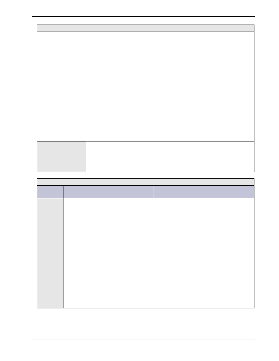
Table 24 Shunt Type Configuration
Shunt
Type
System Configuration
Controller Operation
Battery
Shunt input is connected to a centralized
battery shunt located in the system. All
battery current flows through this shunt
to and from the system batteries. System
may or may not have Shunt Monitors
configured.
Controller reports the following:
I
Load
= Σ I
Rect
+ I
plantshunt
I
battery
= I
plantshunt
Where I
plantshunt
is negative for current into the
battery and positive for current out of the
battery.
If there are shunt monitor cards also installed:
1. Cards configured as monitoring a “Load”
shunt do not affect the total I
Load
but have
their values individually displayed.
2. Cards configured as monitoring a “Battery”
shunt do not contribute to total battery
current ( I
battery
) but have their values
individually displayed.
All battery management functions remain
available.