Table 7 power and sense connector – GE Industrial Solutions Pulsar Plus Controller User Manual
Page 38
Pulsar Plus Controller Family
Issue 7 December 2011
38
Connect to the Controller
Step
Action
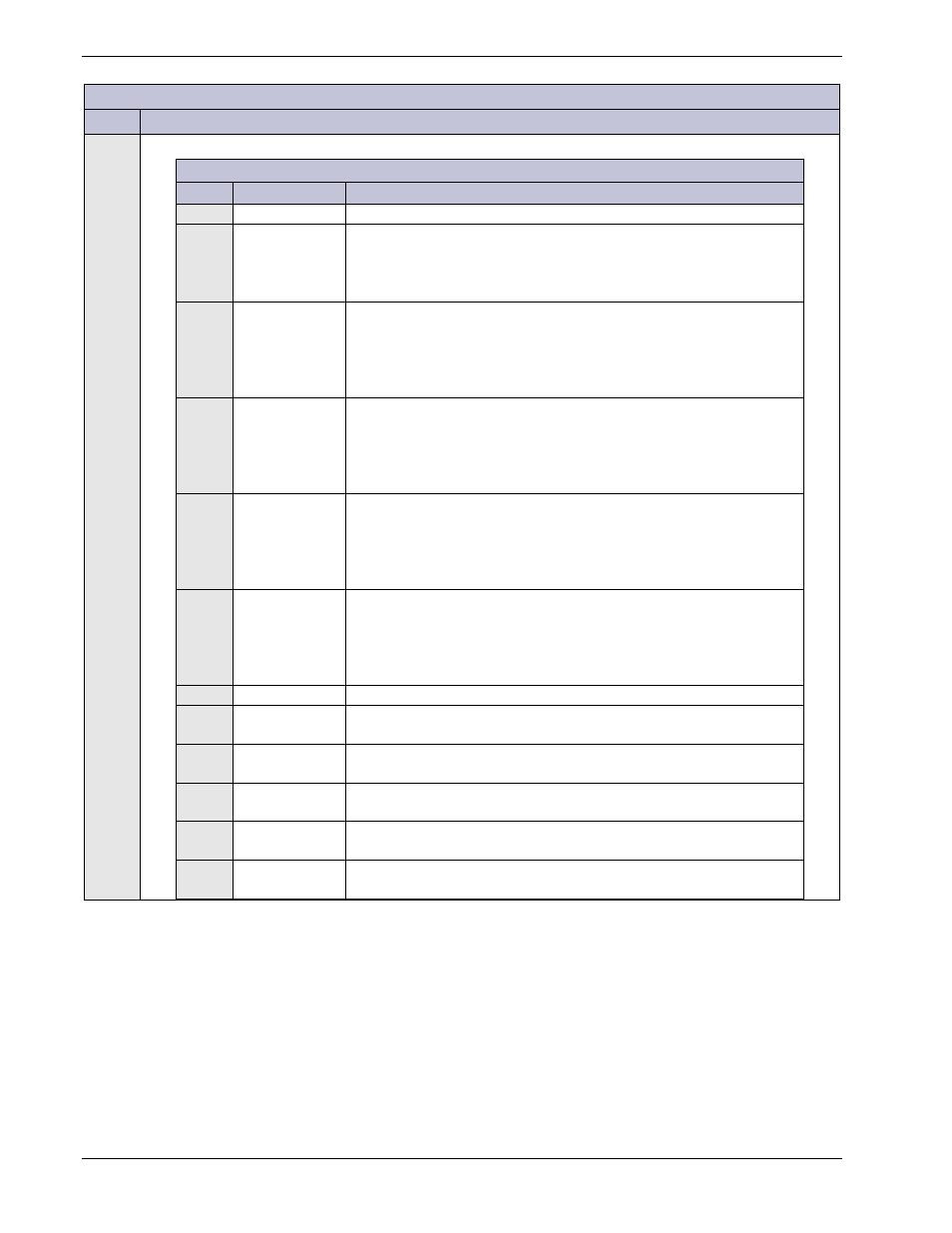
Table 7 Power And Sense Connector
Pin # Signal Name
Description
1
RS485+
“B” side of the RS485 differential pair.
2
GP_REF
Reference lead for the RS485 rectifier GP bus. Must be connected to
the reference side of internal communication circuitry in the rectifier.
• DC Return bus (DG/Ground) in Infinity NE
• Negative 48V DC bus (BAT) in CP/EPS
3
V2SNS_BAT
Second Sense Voltage connected to appropriate non-grounded sided
of the second DC bus (BAT) to provide voltage sense.
In NE Power Systems this connection is connected to negative DC bus
of a -48V system.
4
V2SNS_DG
Second Sense Voltage connected to appropriate return/grounded
side of the second DC bus (DG) to provide voltage sense.
In NE Power Systems this connection is connected to positive DC bus
of a -48V system which is also return/DG.
5
V1SNS_DG
Primary Sense Voltage connected to appropriate return/grounded
side of the primary DC bus (DG) to provide voltage sense.
In NE Power Systems this connection is connected to negative DC bus
of a +24V system which is also return/DG.
6
V1SNS_BAT
Primary Sense Voltage connected to appropriate non-grounded sided
of the primary DC bus (BAT) to provide voltage sense.
In NE Power Systems this connection is connected to positive DC bus
of a +24V system (BAT).
7
RS485-
“A” side of the RS485 differential pair.
8
DG
Reference connection to the Grounded/return side of the DC bus for
alarms.
9
V2-
Connection to the negative potential of the secondary DC bus for
secondary input power.
10
V2+
Connection to the positive potential of the secondary DC bus for
secondary input power.
11
V1-
Connection to the negative potential of the primary DC bus for the
main input power.
12
V1+
Connection to the positive potential of the primary DC bus for main
input power.