Table 9 status leds - dedicated - phoenix, Table 10 status leds - custom assignable - phoenix – GE Industrial Solutions Pulsar Plus Controller User Manual
Page 58
Pulsar Plus Controller Family
Issue 7 December 2011
58
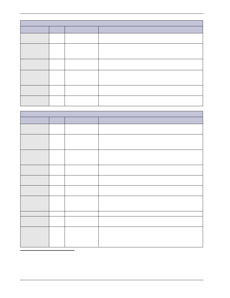
Table 9 Status LEDs - Dedicated - Phoenix
LED
2
Color
Alarm Name
Condition
SYSOK
(NORM)
Green System OK
System OK - Normal operation, no alarms, inputs and
outputs are in their normal range.
PMN
3
Amber Minor Alarm
Medium severity - Generally assigned to alarms which
indicate a non-power affecting condition. Attention
eventually required.
PMJ
Red
Major Alarm
High severity - Generally assigned to alarms which indicate
a power affecting condition. Immediate attention required.
PCR
Red
Critical Alarm
Highest severity - Generally assigned to alarms which
indicate a power affecting condition. Immediate attention
required.
FLOAT
Green Float Mode
One or more of the following alarms are present: Fuse
Minor 48, Fuse Minor 24
EQL
Amber
Equalize / Boost
Mode
One or more of the following alarms are present: Open
String, LVBD Open, Fuse Major 48, Fuse Major 24
Table 10 Status LEDs - Custom Assignable - Phoenix
4
LED
5
Color
Alarm Name
Condition
TCA
Amber
Total Current
Alarm
Plant load current exceeds configured distribution current
rating.
TCOMP
(TEMP COMP)
Amber
Temperature
Compensation
Active
System voltage has been increased or decreased by the
configured Temperature Compensation feature.
BAT
Amber
Battery
Temperature
Alarm
Battery temperature is above the configured threshold.
DCA
Amber
Distribution
Current Alarm
Distribution branch current exceeds the configured
threshold.
CFA
Red
Converter Fail
Alarm
A DC/DC converter has failed.
DFA
(FAJ)
Red
Distribution Fuse
Alarm
A distribution or battery fuses or circuit breakers is open.
LVD
Red
Low Voltage
Disconnect
Alarm
A battery contactor is open due to plant voltage lower than
the configured threshold.
(USR1)
Amber
User configurable LED.
TEMP
Amber
Temperature
Alarm
Ambient temperature is not within configured thresholds.
LMR
Amber
Limited Recharge
Alarm
Load current exceeds the configured % of rectifier capacity
during normal operation.
Alternatively, when load exceeds that of a configured
number of redundant rectifiers.
2
LED labels in parentheses indicate alternate designations not printed on the display label.
3
The highest severity in the system will take precedence.
4
LED labels are printed on the Front Panel. When custom assigned, place an appropriate label over the printed LED
designation.
5
LED labels in parentheses indicate alternate designations not printed on the Front Panel.