Front panel menu structure – GE Industrial Solutions Pulsar Plus Controller User Manual
Page 63
Pulsar Plus Controller Family
Issue 7 December 2011
63
Front Panel Menu Structure
Feature content at the front panel is functionally divided at the Main Menu into the following categories:
Alarms
Warnings
Status
Control/Operations
History
Configuration
Access to the main menu starts at the default front panel screen shown below.
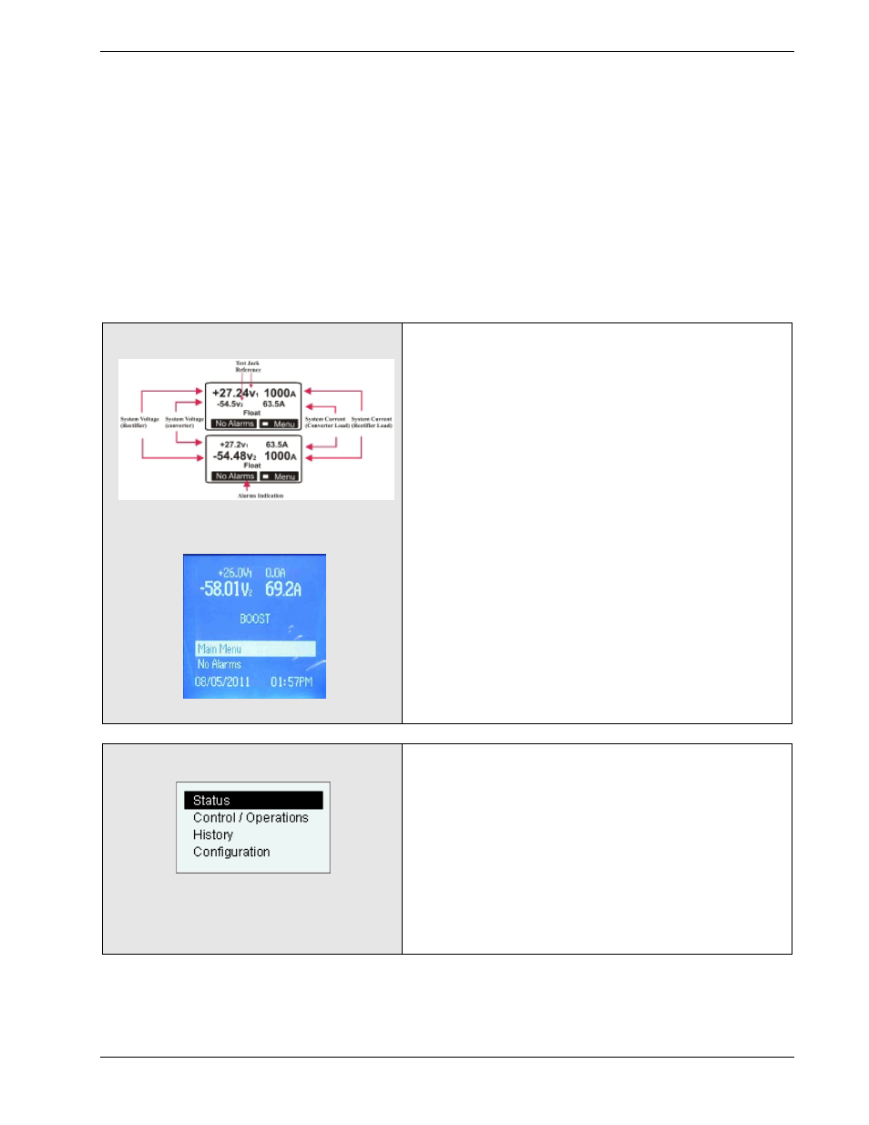
Front Panel Default Screen
The front panel default screen displays the primary
(Rectifier) and secondary (Converter when present) system
bus voltages along with their respective total load in two
different fonts. The larger font represents the rectifier
output. Converter output voltages are also shown with
one decimal extension and rectifier outputs have two
decimal points. V1 represents +24V and V2 represents -
48V systems. Test Jacks V1 and V2 provide access to these
output voltages, respectively.
The operating mode of the system is also displayed.
Possible operating modes are: Float, Battery On Discharge,
Boost, etc.
An alarm soft-key as well as the back-light or status LED
will indicate when alarms are present. Pressing the will
access the alarm cut-off as well as the alarms and warnings
present in the system.
Pressing the button accesses the main menu and the
feature categories previously listed.
Main Menu
Access to alarms, warnings, equipment status detail, basic
control and operations for maintenance purposes, and
system configuration can be obtained.
Note: the controller has the ability to have a front Panel
Password that limits configuration as well as some
operations. A person with administrator level access can
enable this feature through the remote interfaces.
Standard controllers are shipped from the factory with this
feature disabled.