1 input capture trigger source, Atmega4hvd/8hvd – Rainbow Electronics ATmega8HVD User Manual
Page 79
79
8052B–AVR–09/08
ATmega4HVD/8HVD
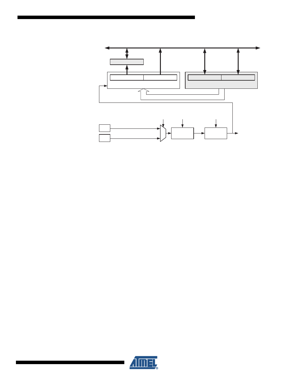
Figure 16-4. Input Capture Unit Block Diagram
The Output Compare Register OCRnA is a dual-purpose register that is also used as an 8-bit
Input Capture Register ICRn. In 16-bit Input Capture mode the Output Compare Register
OCRnB serves as the high byte of the Input Capture Register ICRn. In 8-bit Input Capture
mode the Output Compare Register OCRnB is free to be used as a normal Output Compare
Register, but in 16-bit Input Capture mode the Output Compare Unit cannot be used as there
are no free Output Compare Register(s). Even though the Input Capture register is called
ICRn in this section, it is referring to the Output Compare Register(s). For more information on
how to access the 16-bit registers refer to
”Accessing Registers in 16-bit Mode” on page 82
.
When a change of the logic level (an event) occurs on the Input Capture pin (ICPx), and this
change confirms to the setting of the edge detector, a capture will be triggered. When a cap-
ture is triggered, the value of the counter (TCNTn) is written to the Input Capture Register
(ICRn). The Input Capture Flag (ICFn) is set at the same system clock as the TCNTn value is
copied into Input Capture Register. If enabled (TICIEn=1), the Input Capture Flag generates
an Input Capture interrupt. The ICFn flag is automatically cleared when the interrupt is exe-
cuted. Alternatively the ICFn flag can be cleared by software by writing a logical one to its I/O
bit location.
16.6.1
Input Capture Trigger Source
The default trigger source for the Input Capture unit is the I/O port PC0 in Timer/Counter0 and
the Battery Protection Interrupt in Timer/Counter1. Alternatively can the osi_posedge pin on
the Oscillator Sampling Interface in Timer/Counter0 and Voltage Regulator Interrupt in
Timer/Counter1 be used as trigger sources. The osi_posedge pin in Timer/Counter0 Control
Register A (TCCR0A) and the Voltage Regulator Interrupt bit in the Timer/Counter1 Control
Register A (TCCR1A) is selected as trigger sources by setting the Input Capture Select
(ICS0/1) bit. Be aware that changing trigger source can trigger a capture. The Input Capture
Flag must therefore be cleared after the change.
Both Input Capture inputs are sampled using the same technique. The edge detector is also
identical. However, when the noise canceler is enabled, additional logic is inserted before the
edge detector, which increases the delay by four system clock cycles. An Input Capture on
Timer/Counter0 can also be triggered by software by controlling the port of the PC0 pin.
ICFn
(Int.Req.)
WRITE
ICRn
(16-bit Register)
OCRnB
(8-bit)
Noise
Canceler
ICPn0
Edge
Detector
TEMP
(8-bit)
DATA BUS
(8-bit)
OCRnA
(8-bit)
TCNTn
(16-bit Counter)
TCNTnH
(8-bit)
TCNTnL
(8-bit)
ICNCn
ICESn
ICPn1
ICSn