Atmega4hvd/8hvd – Rainbow Electronics ATmega8HVD User Manual
Page 30
30
8052B–AVR–09/08
ATmega4HVD/8HVD
• Bit 7 – CLKPCE: Clock Prescaler Change Enable
The CLKPCE bit must be written to logic one to enable change of the CLKPS bits. The CLK-
PCE bit is only updated when the other bits in CLKPR are simultaneously written to zero.
CLKPCE is cleared by hardware four cycles after it is written or when CLKPS bits are written.
Rewriting the CLKPCE bit within this time-out period does neither extend the time-out period,
or clear the CLKPCE bit.
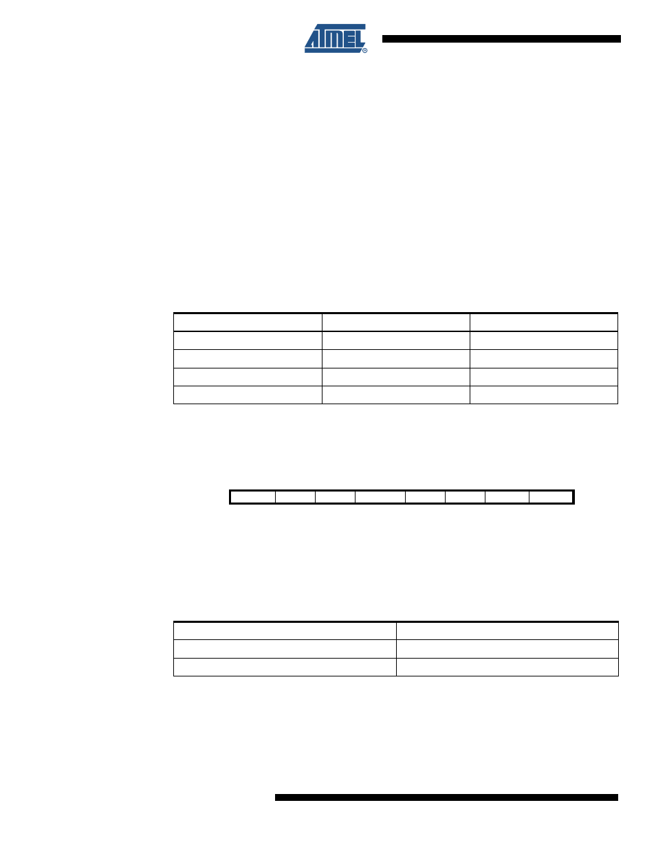
• Bit 1:0 – CLKPS1:0: Clock Prescaler Select Bit 1..0
These bits define the division factor between the selected clock source and the internal sys-
tem clock. These bits can be written run-time to vary the clock frequency to suit the application
requirements. As the divider divides the master clock input to the MCU, the speed of all syn-
chronous peripherals is reduced when a division factor is used. The division factors are given
in
Table 8-4 on page 30
. Note that writing to the System Clock Prescaler Select bits will abort
any ongoing ADC conversion.
Note:
1. Reserved values should not be written to CLKPS1..0
8.13.4
OSICSR – Oscillator Sampling Interface Control and Status Register
• Bits 7:5,3:2 – RES: Reserved bits
These bits are reserved bits in the ATmega4HVD/8HVD and will always read as zero.
• Bit 4 - OSISEL0: Oscillator Sampling Interface Select 0
• Bit 1 – OSIST: Oscillator Sampling Interface Status
This bit continuously displays the phase of the prescaled clock. This bit can be polled by the
CPU to determine the rising and falling edges of the prescaled clock.
Table 8-4.
System Clock Prescaler Select
CLKPS1
CLKPS0
Clock Division Factor
0
0
Reserved
(1)
0
1
2
1
0
4
1
1
8
Bit
7
6
5
4
3
2
1
0
–
–
–
OSISEL0
–
–
OSIST
OSIEN
OSICSR
Read/Write
R
R
R
R/W
R
R
R
R/W
Initial Value
0
0
0
0
0
0
0
0
Table 8-5.
OSISEL Bit Description
OSISEL0
Oscillator source
0
ULP Oscillator
1
Slow RC Oscillator