2 fet driver, 1 features, 2 overview – Rainbow Electronics ATmega8HVD User Manual
Page 115: Atmega4hvd/8hvd
115
8052B–AVR–09/08
ATmega4HVD/8HVD
21.2
FET Driver
21.2.1
Features
•
Charge-pump for generating suitable gate drive for N-Channel FET switch on high side
•
Deep Under-voltage Recovery mode that allows normal operation while charging a Deeply
Over-discharged battery from 0-volt
21.2.2
Overview
The ATmega4HVD/8HVD includes a FET Driver. The FET Driver is designed for driving N-
channel FETs used as high side switch in 1-Cell Li-Ion battery pack. A block diagram of the
FET driver is shown in
Figure 21-2
.
When charging deeply over-discharged cells, the FET Driver will be operated in Deep Under-
Voltage Recovery (DUVR) mode. In DUVR mode the FET Driver regulates the voltage at the
VFET pin to typically 2.3 Volts in 1-Cell applications. This is done by operating the Charge
FET at a point where the drain-source voltage is equal to the voltage difference between the
cell voltage and the required VFET operating voltage. As the cell voltage increases, the drain-
source voltage of the Charge FET will decrease until the Charge FET is completely on. See
for details.
In normal operation (DUVRD = 1), the Charge FET/Discharge FET is switched on by pumping
OC/OD sufficiently above the VFET supply voltage. To turn off the Charge FET/Discharge
FET, OC/OD is pulled quickly low. See
and
for details..
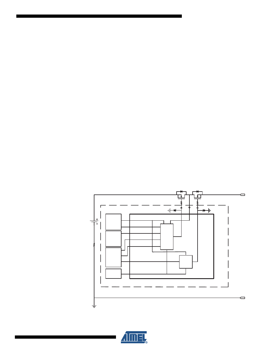
Figure 21-2. FET Driver block diagram.
Discharge FET
Charge FET
OD
OC
BATT+
BATT-
VFET
NFET DRIVER
DUVRD
D-FET
Charge
Pump
CHARGE_EN
DISCHARGE_EN
FET
CONTROL
C-FET
Charge
Pump
DUALC_MODE
LDO
_VREG
DVDD
VREF
BANDGAP
REF.
CLK
CLK_OSC
1k
1k
14V clamp
14V clamp