2 low byte, 3 latching of fuses, 3 signature bytes – Rainbow Electronics ATmega8HVD User Manual
Page 130: Atmega4hvd/8hvd
130
8052B–AVR–09/08
ATmega4HVD/8HVD
Note:
1. The default OSCSEL1:0 setting should not be changed. OSCSEL1:0 = ‘00’ is reserved for
test purposes. Other values are reserved for future use.
24.2.2
Low Byte
Notes:
1. See
Table 8-1 on page 23
for details about start-up time.
2. The SPIEN Fuse is not accessible in SPI programming mode.
3. See
”WDTCSR – Watchdog Timer Control Register” on page 48
for details.
The status of the Fuse bits is not affected by Chip Erase. Note that the Fuse bits are locked if
Lock bit1 (LB1) is programmed. Program the Fuse bits before programming the Lock bits.
24.2.3
Latching of Fuses
The fuse values are latched when the device enters programming mode and changes of the
fuse values will have no effect until the part leaves Programming mode. This does not apply to
the EESAVE Fuse which will take effect once it is programmed. The fuses are also latched on
Power-up in Normal mode.
24.3
Signature Bytes
All Atmel microcontrollers have a three-byte signature code which identifies the device. This
code can be read in both Programming mode, also when the device is locked. The three bytes
reside in a separate address space. The signature bytes of ATmega4HVD/8HVD is given in
Table 24-5
.
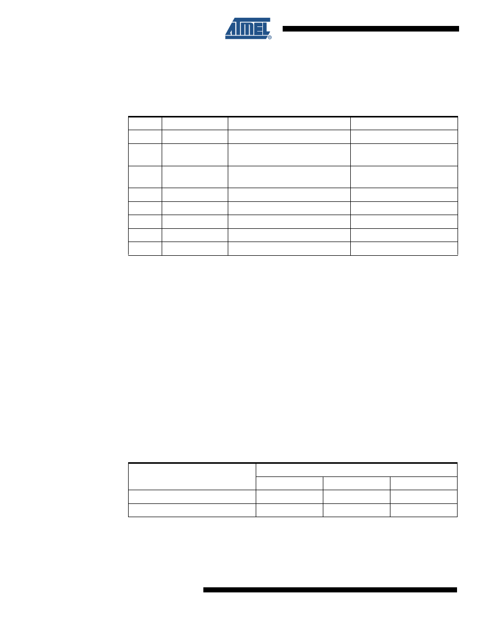
Table 24-4.
Fuse Low Byte
Bit No
Fuse Low Byte
Description
Default Value
7
WDTON
(3)
Watchdog Timer always on
1 (unprogrammed)
6
EESAVE
EEPROM memory is preserved
through the Chip Erase
1 (unprogrammed, EEPROM
not preserved)
5
SPIEN
(2)
Enable SPI Programming Interface
0 (programmed, SPI prog.
enabled)
4
DWEN
Enable debugWIRE
1 (unprogrammed)
3
SELFPRGEN
Self Programming enable
1 (unprogrammed)
2
SUT2
(1)
Select start-up time
1 (unprogrammed)
1
SUT1
(1)
Select start-up time
1 (unprogrammed)
0
SUT0
(1)
Select start-up time
1 (unprogrammed)
Table 24-5.
Device ID
Part
Signature Bytes Address
0x000
0x001
0x002
ATmega4HVD
0x1E
TBD
TBD
ATmega8HVD
0x1E
0x93
0x12