Debugwire on-chip debug system, 1 features, 2 overview – Rainbow Electronics ATmega8HVD User Manual
Page 119: 3 physical interface, Atmega4hvd/8hvd
119
8052B–AVR–09/08
ATmega4HVD/8HVD
22. debugWIRE On-chip Debug System
22.1
Features
•
Complete Program Flow Control
•
Emulates All On-chip Functions, both Digital and Analog, except RESET Pin
•
Real-time Operation
•
Symbolic Debugging Support (Both at C and Assembler Source Level, or for Other HLLs)
•
Unlimited Number of Program Break Points (Using Software Break Points)
•
Non-intrusive Operation
•
Electrical Characteristics Identical to Real Device
•
Automatic Configuration System
•
High-Speed Operation
•
Programming of Non-volatile Memories
22.2
Overview
The debugWIRE On-chip debug system uses a One-wire, bi-directional interface to control the
program flow, execute AVR instructions in the CPU and to program the different non-volatile
memories.
22.3
Physical Interface
When the debugWIRE Enable (DWEN) Fuse is programmed and Lock bits are unpro-
grammed, the debugWIRE system within the target device is activated. The RESET port pin is
configured as a wire-AND (open-drain) bi-directional I/O pin with pull-up enabled and becomes
the communication gateway between target and emulator.
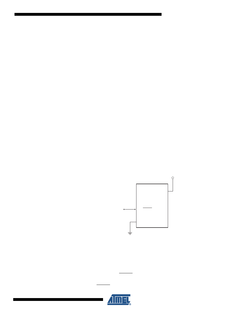
Figure 22-1. The debugWIRE Setup
Figure 22-1
shows the schematic of a target MCU, with debugWIRE enabled, and the emula-
tor connector. The system clock is not affected by debugWIRE and will always be the clock
source selected by the CKSEL Fuses.
When designing a system where debugWIRE will be used, the following observations must be
made for correct operation:
• Pull-up resistors on the dW/(RESET) line must not be smaller than 10k
Ω
. The pull-up
resistor is not required for debugWIRE functionality.
• Connecting the RESET pin directly to V
CC
will not work.
dW
GND
dW(RESET)
VFET
2.1 - 6.0V