Atmega4hvd/8hvd – Rainbow Electronics ATmega8HVD User Manual
Page 44
44
8052B–AVR–09/08
ATmega4HVD/8HVD
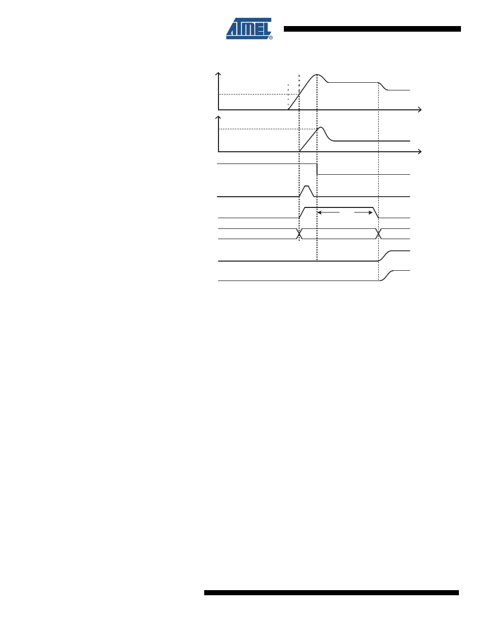
Figure 10-9. Powering up ATmega4HVD/8HVD (2-FET example)
During the initial start-up when a valid reference for the voltage regulator is missing, VCC is
driven as close as possible to VFET. Voltage regulation will only start when VCC has reached
VBLOT, start-up, which represents the voltage level that guarantees proper start-up conditions
for the voltage regulator.
Even though the voltage regulator has started up and the digital part is powered, the chip is
kept in the RESET state and cell charging is disabled until VCC exceeds V
BLOT, start-up
. The
time from a charger is connected until this happens is very short in the two- FET application
(actual timing depends on the CREG value). Once the condition VCC > V
BLOT, start-up is
met,
BLOD is released and the Reset Delay counter starts counting. For details, see
Deep Under-Voltage Recovery Mode operation” on page 117
.
VCC will now be regulated to its nominal value. The Reset Delay counter makes sure that the
chip is continuously kept in RESET state internally for a time corresponding to the start-up
time selected by the SUT fuses (time indicated as t
TOUT
in
Figure 10-9 on page 44
).
Power-off
CHIP STATE
POR
V
BATT
INTERNAL_RESET
t
TOUT
Reset
Active
V
POT
V
CC
2.2 V
V
BLOT, START-UP
BLOD
CHARGER CONNECTED
CHARGER DETECTED
OD
OC