System clock and clock options, 1 clock systems and their distribution, 1 cpu clock – clkcpu – Rainbow Electronics ATmega8HVD User Manual
Page 22: 2 i/o clock – clki/o, 3 flash clock – clkflash, 4 adc clock – clkadc, Atmega4hvd/8hvd
22
8052B–AVR–09/08
ATmega4HVD/8HVD
8.
System Clock and Clock Options
8.1
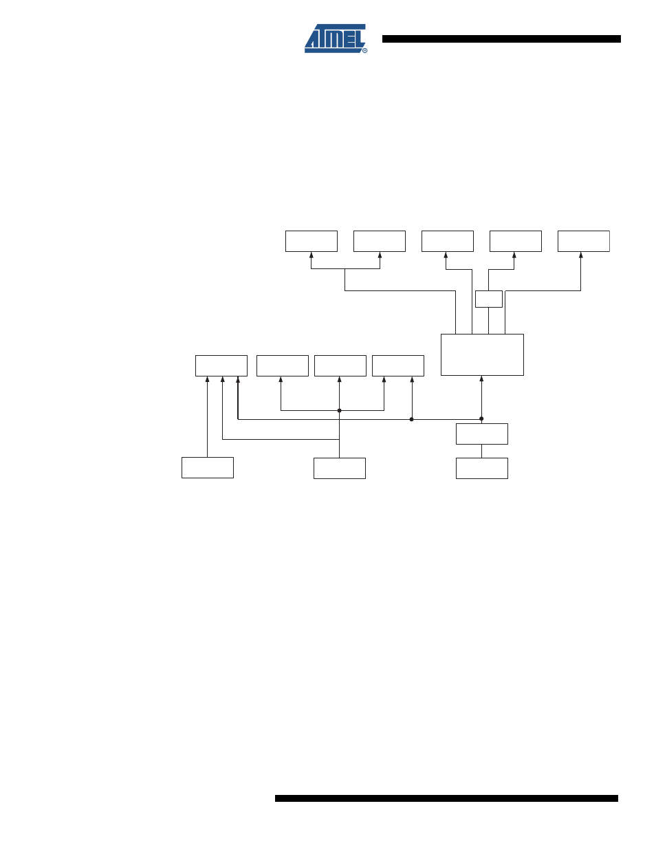
Clock Systems and their Distribution
Figure 8-1
presents the principal clock systems in the AVR and their distribution. All of the
clocks need not be active at a given time. In order to reduce power consumption, the clocks to
modules not being used can be halted by using different sleep modes, as described in
Management and Sleep Modes” on page 32
. The clock systems are detailed below.
Figure 8-1.
Clock Distribution
8.1.1
CPU Clock – clk
CPU
The CPU clock is routed to parts of the system concerned with operation of the AVR core.
Examples of such modules are the General Purpose Register File, the Status Register and the
data memory holding the Stack Pointer. Halting the CPU clock inhibits the core from perform-
ing general operations and calculations.
8.1.2
I/O Clock – clk
I/O
The I/O clock is used by the majority of the I/O modules. The I/O clock is also used by the
External Interrupt module, but note that some external interrupts are detected by asynchro-
nous logic, allowing such interrupts to be detected even if the I/O clock is halted.
8.1.3
Flash Clock – clk
FLASH
The Flash clock controls operation of the Flash interface. The Flash clock is usually active
simultaneously with the CPU clock.
8.1.4
ADC Clock – clk
ADC
The ADC is provided with a dedicated clock domain. The ADC is automatically prescaled
according to the System Clock Prescaler's setting to provide a fixed clock frequency to the
Ultra Low Power
RC Oscillator
Watchdog Timer
Battery Protection
Reset Logic
CPU
CORE
RAM
FLASH and
EEPROM
Voltage
ADC
Other I/O
Modules
AVR
Clock Control
Fast RC
Oscillator
clk
CPU
clk
FLASH
clk
VADC
clk
I/O
System Clock
Prescaler
ADC
Prescaler
Oscillator Sampling
Interface
Slow RC
Oscillator