3 system and reset characteristics, 4 external interrupts characteristics, System and – Rainbow Electronics ATmega8HVD User Manual
Page 144: Will ge, One detec, Will generate an, Atmega4hvd/8hvd
144
8052B–AVR–09/08
ATmega4HVD/8HVD
26.3
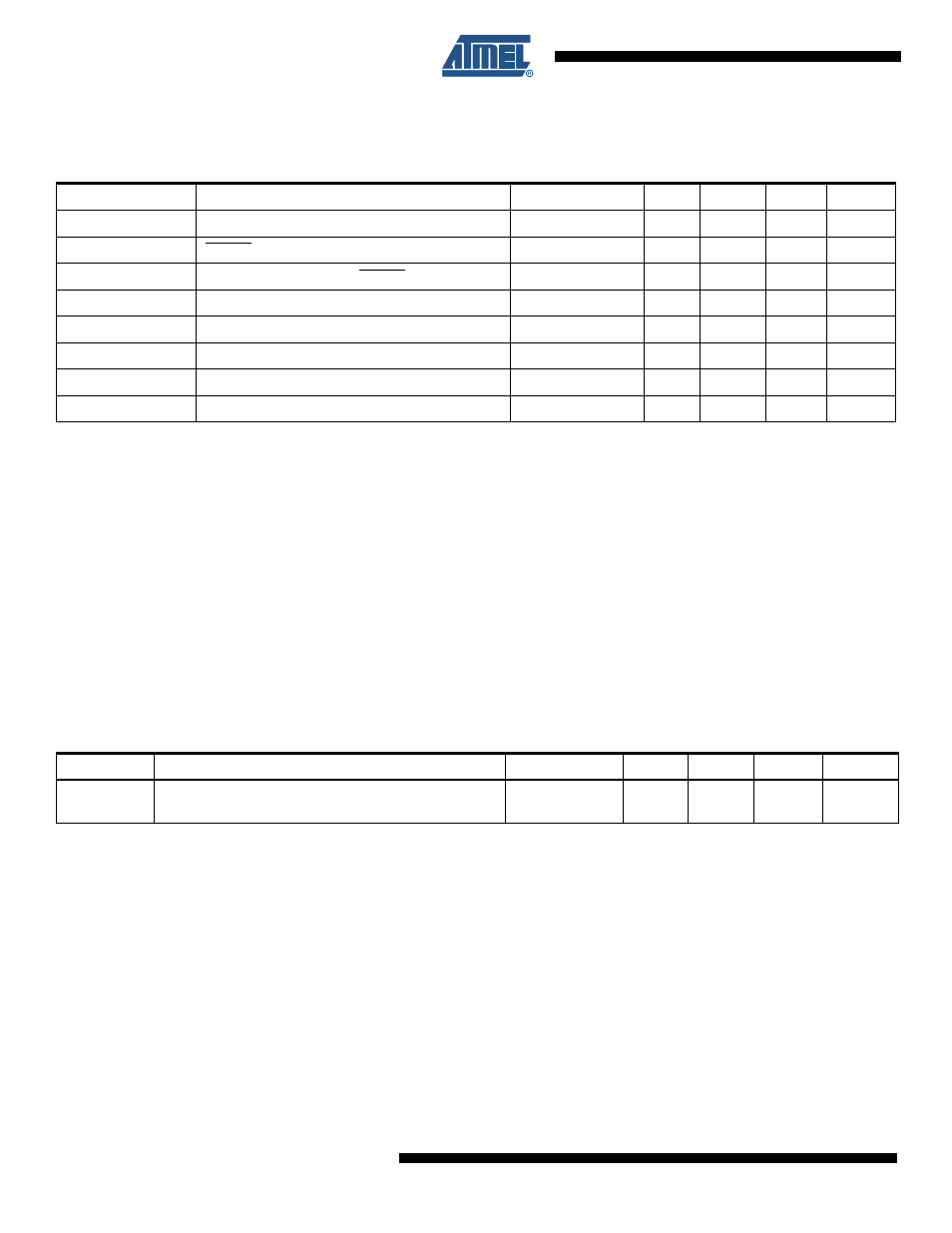
System and Reset Characteristics
Notes:
1. Values are guidelines only. Actual values are TBD.
2. Not tested in production.
3. The ATmega4HVD/8HVD will start up when the voltage at the BATT pin exceeds V
POT
.
4. The BATT pin monitors the charger voltage. Because of the voltage drop across the body diode of the Discharge FET, the
supply voltage at the VFET pin is approximately 0.5V below the V
POT
level when the ATmega4HVD/8HVD starts up. That is
why typical V
POT
level is set to 3.0V.
5. V
BLOT
may be below nominal minimum operating voltage for some devices. For devices where this is the case, the device is
tested down to V
REG
= V
BLOT, NORMAL
during the production test. This guarantees that a Black-out Reset will occur before V
CC
drops to a voltage where correct operation of the microcontroller is no longer guaranteed. The Black-out detector monitors
the output voltage of the regulator, VREG. V
BLOT
level is therefore not directly related to the V
POT
level.
6. In normal operation, the BLOD detection level will always be lower than the minimum voltage regulator output voltage when
the voltage regulator is operated within its specifications.
26.4
External Interrupts Characteristics
Table 26-2.
Power-on, Reset, BLOD, and Voltage Reference Characteristics
, T
A
= -20°C to 85°C, VFET = 2.4 to 4.2V
(unless otherwise noted)
Symbol
Parameter
Condition
Min
Typ
Max
Units
V
POT
Power-on Threshold Voltage
(3)
2.5
3.0
(4)
3.4
V
V
RST
RESET Pin Threshold Voltage
VREG = 2.2V
0.4
1.9
V
t
RST
Minimum pulse width on RESET Pin
900
ns
V
BLOT, NORMAL
BLOD Threshold Voltage
1.7
1.8
2.0
V
V
BLOT, START-UP
BLOD Threshold Voltage
2.3
2.5
V
t
BLOD
Min Pulse Width on Black-out Reset
2
µs
t
BLODTOUT
Black-out Power-off Delay
4
CK
V
REF
Bandgap reference voltage after calibration
1.03
1.1
1.17
V
Table 26-3.
Asynchronous External Interrupt Characteristics, T
A
= -20°C to 85°C, VFET = 2.4 to 4.2V (unless otherwise
noted)
Symbol
Parameter
Condition
Min
Typ
Max
Units
t
INT
Minimum pulse width for asynchronous external
interrupt
50
ns