1 registers, 2 definitions, 3 timer/counter clock sources – Rainbow Electronics ATmega8HVD User Manual
Page 75: 4 counter unit, Atmega4hvd/8hvd
75
8052B–AVR–09/08
ATmega4HVD/8HVD
16.2.1
Registers
The Timer/Counter Low Byte Register (TCNTnL) and Output Compare Registers (OCRnA and
OCRnB) are 8-bit registers. Interrupt request (abbreviated to Int.Req. in
Figure 16-1 on page
74
) signals are all visible in the Timer Interrupt Flag Register (TIFR). All interrupts are individu-
ally masked with the Timer Interrupt Mask Register (TIMSK). TIFR and TIMSK are not shown
in the figure.
In 16-bit mode the Timer/Counter consists one more 8-bit register, the Timer/Counter High
Byte Register (TCNTnH). Furthermore, there is only one Output Compare Unit in 16-bit mode
as the two Output Compare Registers, OCRnA and OCRnB, are combined to one 16-bit Out-
put Compare Register. OCRnA contains the low byte of the word and OCRnB contains the
higher byte of the word. When accessing 16-bit registers, special procedures described in sec-
tion
”Accessing Registers in 16-bit Mode” on page 82
The Timer/Counter can be clocked internally, via the prescaler, or by an external clock source
on the Tn pin. The Clock Select logic block controls which clock source and edge the
Timer/Counter uses to increment its value. The Timer/Counter is inactive when no clock
source is selected. The output from the Clock Select logic is referred to as the timer clock
(clk
Tn
).
16.2.2
Definitions
Many register and bit references in this section are written in general form. A lower case “n”
replaces the module number, e.g. Timer/Counter number. A lower case “x” replaces the unit,
e.g. OCRnx and ICPnx describes OCRnA/B and ICP1/0x . However, when using the register
or bit defines in a program, the precise form must be used, i.e., TCNT0L for accessing
Timer/Counter0 counter value and so on.
The definitions in
Table 16-1
are also used extensively throughout the document.
16.3
Timer/Counter Clock Sources
The Timer/Counter can be clocked internally, via the prescaler, or by an external clock source.
The Clock Select logic is controlled by the Clock Select (CSn2:0) bits located in the
Timer/Counter Control Register n B (TCCRnB), and controls which clock source and edge the
Timer/Counter uses to increment its value. The Timer/Counter is inactive when no clock
source is selected. The output from the Clock Select logic is referred to as the timer clock
(clk
Tn
). For details on clock sources and prescaler, see
”Timer/Counter0 and Timer/Counter1
16.4
Counter Unit
The main part of the 8-bit Timer/Counter is the programmable bi-directional counter unit.
Fig-
ure 16-2 on page 76
shows a block diagram of the counter and its surroundings.
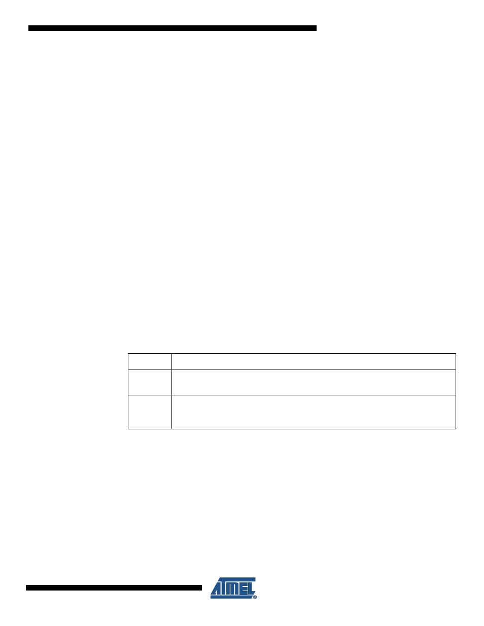
Table 16-1.
Definitions
BOTTOM
The counter reaches the BOTTOM when it becomes 0.
MAX
The counter reaches its MAXimum when it becomes 0xFF (decimal 255) in 8-bit mode
or 0xFFFF (decimal 65535) in 16-bit mode.
TOP
The counter reaches the TOP when it becomes equal to the highest value in the count
sequence. The TOP value can be assigned to be the fixed value 0xFF/0xFFFF (MAX) or
the value stored in the OCRnA Register.