Atmega4hvd/8hvd – Rainbow Electronics ATmega8HVD User Manual
Page 49
49
8052B–AVR–09/08
ATmega4HVD/8HVD
If WDE is set, the Watchdog Timer is in Interrupt and System Reset Mode. The first timeout in
the Watchdog Timer will set WDIF. Executing the corresponding interrupt vector will clear
WDIE and WDIF automatically by hardware (the Watchdog goes to System Reset Mode). This
is useful for keeping the Watchdog Timer security while using the interrupt. To stay in Interrupt
and System Reset Mode, WDIE must be set after each interrupt. This should however not be
done within the interrupt service routine itself, as this might compromise the safety-function of
the Watchdog System Reset mode. If the interrupt is not executed before the next timeout, a
System Reset will be applied.
Note:
1. WDTON Fuse set to “0” means programmed, “1” means unprogrammed.
• Bit 5, 2..0 - WDP3..0 : Watchdog Timer Prescaler 3, 2, 1 and 0
The WDP3..0 bits determine the Watchdog Timer prescaling when the Watchdog Timer is
enabled. The different prescaling values and their corresponding Timeout Periods are shown
in
Table 10-2
.
• Bit 4 - WDCE: Watchdog Change Enable
This bit is used in timed sequences for changing WDE and prescaler bits. To clear the WDE
bit, and/or change the prescaler bits, WDCE and WDE must be written to one. Within the next
four clock cycles, write the WDE and WDP bits as desired, and the WDCE bit cleared.
Once written to one, hardware will clear WDCE after four clock cycles.
• Bit 3 - WDE: Watchdog System Reset Enable
When the WDE bit is written to logic one, the Watchdog Timer is enabled, and if the WDE bit is
written to logic zero, the Watchdog Timer function is disabled. WDE can only be cleared if the
WDCE bit has logic level one, refer to the WDCE bit description.
If the WDTON fuse is programmed, it is not possible to disable the Watchdog Timer. Further-
more, WDE is overridden by WDRF in MCUSR. This means that WDE is always set when
WDRF is set. To clear WDE, WDRF must be cleared first. This feature ensures multiple resets
during conditions causing failure, and a safe start-up after the failure.
• Bits 5, 2..0 – WDP3..0: Watchdog Timer Prescaler 3, 2, 1, and 0
The WDP3..0 bits determine the Watchdog Timer prescaling when the Watchdog Timer is
enabled. The different prescaling values and their corresponding Timeout Periods are shown
in
Table 10-2
.
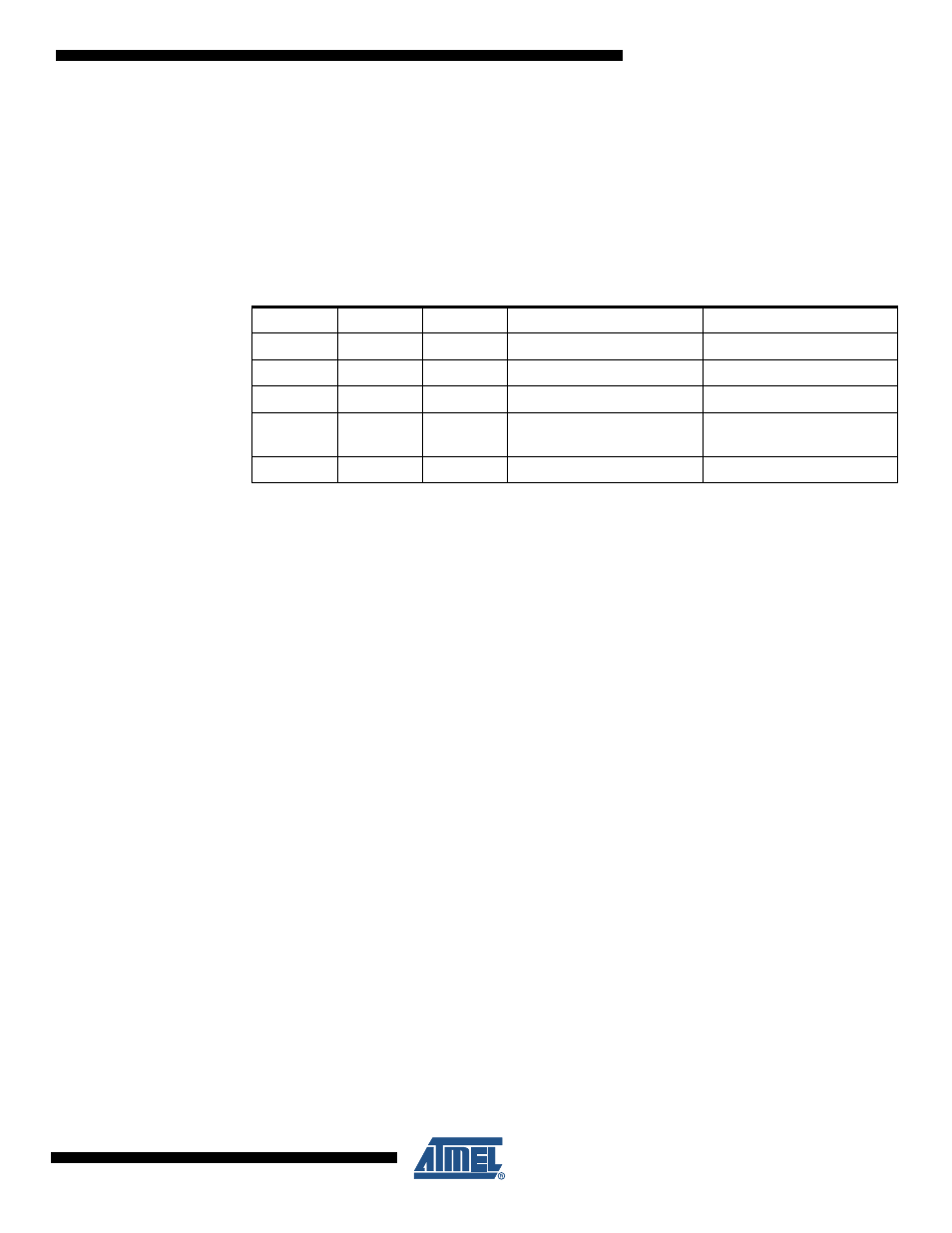
Table 10-1.
Watchdog Timer Configuration
WDTON
WDE
WDIE
Mode
Action on Timeout
1
0
0
Stopped
None
1
0
1
Interrupt Mode
Interrupt
1
1
0
System Reset Mode
Reset
1
1
1
Interrupt and System Reset
Mode
Interrupt, then go to System
Reset Mode
0
x
x
System Reset Mode
Reset