7 watchdog timer, 1 features, Atmega4hvd/8hvd – Rainbow Electronics ATmega8HVD User Manual
Page 45
45
8052B–AVR–09/08
ATmega4HVD/8HVD
10.7
Watchdog Timer
10.7.1
Features
•
Clocked from Slow RC Oscillator
•
3 Operating modes
– Interrupt
– System Reset
– Interrupt and System Reset
•
Selectable Timeout period from 16 ms to 8s
•
Possible Hardware fuse Watchdog always on (WDTON) for fail-safe mode
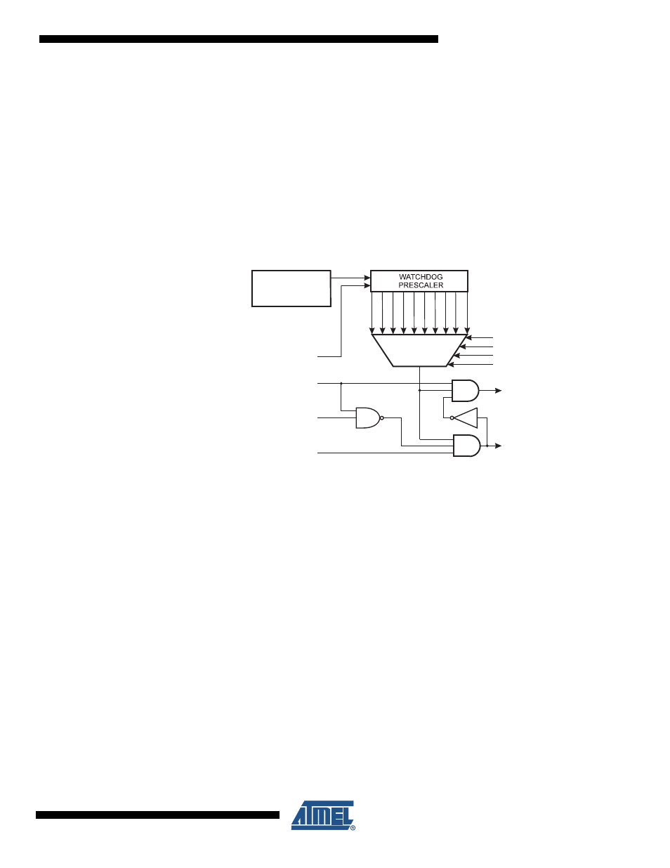
Figure 10-10. Watchdog Timer
ATmega4HVD/8HVD has an Enhanced Watchdog Timer (WDT). The WDT is a timer counting
cycles of the Slow RC Oscillator that runs at 131 kHz (typical value, see
). The WDT gives an interrupt or a system reset when the counter reaches
a given timeout value. In normal operation mode, it is required that the system uses the WDR
- Watchdog Timer Reset - instruction to restart the counter before the timeout value is
reached. If the system doesn't restart the counter, an interrupt or system reset will be issued.
In Interrupt mode, the WDT gives an interrupt when the timer expires. This interrupt can be
used to wake the device from sleep-modes, and also as a general system timer. One example
is to limit the maximum time allowed for certain operations, giving an interrupt when the opera-
tion has run longer than expected. In System Reset mode, the WDT gives a reset when the
timer expires. This is typically used to prevent system hang-up in case of runaway code. The
third mode, Interrupt and System Reset mode, combines the other two modes by first giving
an interrupt and then switch to System Reset mode. This mode will for instance allow a safe
shutdown by saving critical parameters before a system reset.
The Watchdog always on (WDTON) fuse, if programmed, will force the Watchdog Timer to
System Reset mode. With the fuse programmed the System Reset mode bit (WDE) and Inter-
rupt mode bit (WDIE) are locked to 1 and 0 respectively. To further ensure program security,
alterations to the Watchdog set-up must follow timed sequences. The sequence for clearing
WDE and changing timeout configuration is as follows:
Slow RC
OSCILLATOR
16ms
32ms
64ms
125ms
250ms
0.5s
1.0s
2.0s
4.0s
8.0s
WDP0
WDP1
WDP2
WDP3
WATCHDOG
RESET
WDE
WDIF
WDIE
MCU RESET
INTERRUPT