Atmega4hvd/8hvd – Rainbow Electronics ATmega8HVD User Manual
Page 110
110
8052B–AVR–09/08
ATmega4HVD/8HVD
20.8.3
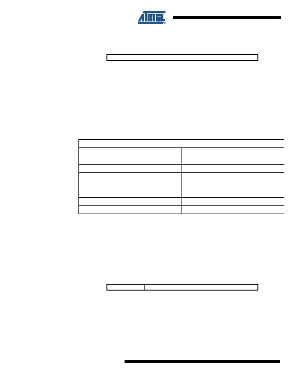
BPSCTR – Battery Protection Short-current Timing Register
• Bit 7 – Res: Reserved Bits
This bit is reserved and will always read as zero.
• Bit 6:0 – SCPT6:0: Short-current Protection Timing
These bits control the delay of the Short-circuit Protection. The Short-circuit Timing can be set
with a step size of 62.5 µs as shown in
Table 20-2 on page 110
.
Notes:
1. The actual value depends on the actual frequency of the
”Ultra Low Power RC Oscillator” on
”Electrical Characteristics” on page 142
2. Initial value: SCPT[0x10](1ms).
3. An additional delay up to T
d
can be expected after enabling the Discharge FET due to initial-
ization of the protection circuit. With nomial ULP frequency this delay is maximum 55 µs.
Note:
Due to synchronization of parameters between clock domains, a guard time of 3 ULP oscillator
cycles + 3 CPU clock cycles is required between each time the BPSCTR register is written. Any
writing to the BPSCTR register during this period will be ignored.
20.8.4
BPOCTR – Battery Protection Over-current Timing Register
• Bit 7:6 – Res: Reserved Bits
These bits are reserved and will always read as zero.
• Bit 5:0 – OCPT5:0: Over-current Protection Timing
These bits control the delay of the Over-circuit Protection. The Over-current Timing can be set
with a step size of 0.5 ms as shown in
Table 20-3 on page 111
.
Bit
7
6
5
4
3
2
1
0
–
SCPT[6:0]
BPSCTR
Read/Write
R
R/W
R/W
R/W
R/W
R/W
R/W
R/W
Initial Value
0
0
0
1
0
0
0
0
Table 20-2.
Short-circuit Protection Reaction Time. SCPT[6:0] with corresponding Short-cir-
cuit Delay Time.
Short-circuit Protection Reaction Time
(1)
SCPT[6:0]
(2)
Typ
0x00
(23.0 - 86.0 µs) + T
d
(3)
0x01
(23.0 - 86.0 µs) + T
d
(3)
0x02
(85.5 - 148.5 µs) + T
d
(3)
0x03
(148.0 - 211.0 µs) + T
d
(3)
...
...
0x7E
(7.84 - 7.90 ms) + T
d
(3)
0x7F
(7.90 - 7.96 ms) + T
d
(3)
Bit
7
6
5
4
3
2
1
0
–
–
OCPT[5:0]
BPOCTR
Read/Write
R
R
R/W
R/W
R/W
R/W
R/W
R/W
Initial Value
0
0
0
0
0
0
1
0