7 battery protection cpu interface, 8 register description, Atmega4hvd/8hvd – Rainbow Electronics ATmega8HVD User Manual
Page 108
108
8052B–AVR–09/08
ATmega4HVD/8HVD
20.7
Battery Protection CPU Interface
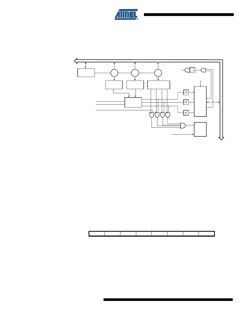
The Battery Protection CPU Interface is illustrated in
Figure 20-2. Battery Protection CPU Interface
Each protection originating from the Current Battery Protection module has an Interrupt Flag.
All enabled flags are combined into a single battery protection interrupt request to the CPU.
This interrupt can wake up the CPU from any operation mode, except Power-off. The interrupt
flags are cleared by writing a logic ‘1’ to their bit locations from the CPU. An interrupt event for
the External Protection Input can be generated by enabling the external interrupt for the input
port.
Note that there are neither flags nor status bits indicating that the chip has entered the Power
Off mode. This is because the CPU is powered down in this mode. The CPU will, however be
able to detect that it came from a Power-off situation by monitoring CPU reset flags when it
resumes operation.
20.8
Register Description
20.8.1
BPPLR – Battery Protection Parameter Lock Register
• Bit 7:2 – Res: Reserved Bits
These bits are reserved and will always read as zero.
3
/
3
/
3
/
Interr
u
pt
Re
qu
e
s
t
Interr
u
pt
Acknowledge
FET
Control
C
u
rrent
B
a
ttery
Protection
B
a
ttery Protection
Control Regi
s
ter
B
a
ttery Protection
Timing Regi
s
ter
B
a
ttery Protection
Level Regi
s
ter
B
a
ttery Protection
P
a
r
a
meter Lock
Regi
s
ter
GND
NI
LOCK?
LOCK?
LOCK?
8
-BIT DATA BU
S
Power-off
B
a
ttery
Protection
Interr
u
pt
Regi
s
ter
B
a
ttery
Protection
EXTPROT
Bit
7
6
5
4
3
2
1
0
–
–
–
–
–
–
BPPLE
BPPL
BPPLR
Read/Write
R
R
R
R
R
R
R/W
R/W
Initial Value
0
0
0
0
0
0
0
0