2 gtccr – general timer/counter control register, Atmega4hvd/8hvd – Rainbow Electronics ATmega8HVD User Manual
Page 73
73
8052B–AVR–09/08
ATmega4HVD/8HVD
If external pin modes are used for the Timer/Counter n, transitions on the Tn pin will clock the
counter even if the pin is configured as an output. This feature allows software control of the
counting.
15.5.2
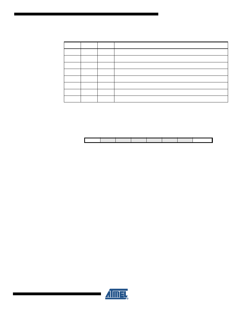
GTCCR – General Timer/Counter Control Register
• Bit 7 – TSM: Timer/Counter Synchronization Mode
Writing the TSM bit to one activates the Timer/Counter Synchronization mode. In this mode,
the value that is written to the PSRSYNC bit is kept, hence keeping the corresponding pres-
caler reset signals asserted. This ensures that the corresponding Timer/Counters are halted
and can be configured to the same value without the risk of one of them advancing during con-
figuration. When the TSM bit is written to zero the PSRSYNC bit is cleared by hardware, and
the Timer/Counters start counting simultaneously.
• Bit 0 – PSRSYNC: Prescaler Reset
When this bit is one, Timer/Counter1 and Timer/Counter0 prescaler will be Reset. This bit is
normally cleared immediately by hardware, except if the TSM bit is set. Note that
Timer/Counter1 and Timer/Counter0 share the same prescaler and a reset of this prescaler
will affect both timers.
Table 15-1.
Clock Select Bit Description
CSn2
CSn1
CSn0
Description
0
0
0
No clock source (Timer/Counter stopped)
0
0
1
clk
I/O
/(No prescaling)
0
1
0
clk
I/O
/8 (From prescaler)
0
1
1
clk
I/O
/64 (From prescaler)
1
0
0
clk
I/O
/256 (From prescaler)
1
0
1
clk
I/O
/1024 (From prescaler)
1
1
0
External clock source on Tn pin. Clock on falling edge.
1
1
1
External clock source on Tn pin. Clock on rising edge.
Bit
7
6
5
4
3
2
1
0
TSM
–
–
–
–
–
–
PSRSYNC
GTCCR
Read/Write
R/W
R
R
R
R
R
R
R/W
Initial Value
0
0
0
0
0
0
0
0