6 atmega4hvd/8hvd start-up sequence, 1 start-up with one fet connected, Atmega4hvd/8hvd – Rainbow Electronics ATmega8HVD User Manual
Page 42
42
8052B–AVR–09/08
ATmega4HVD/8HVD
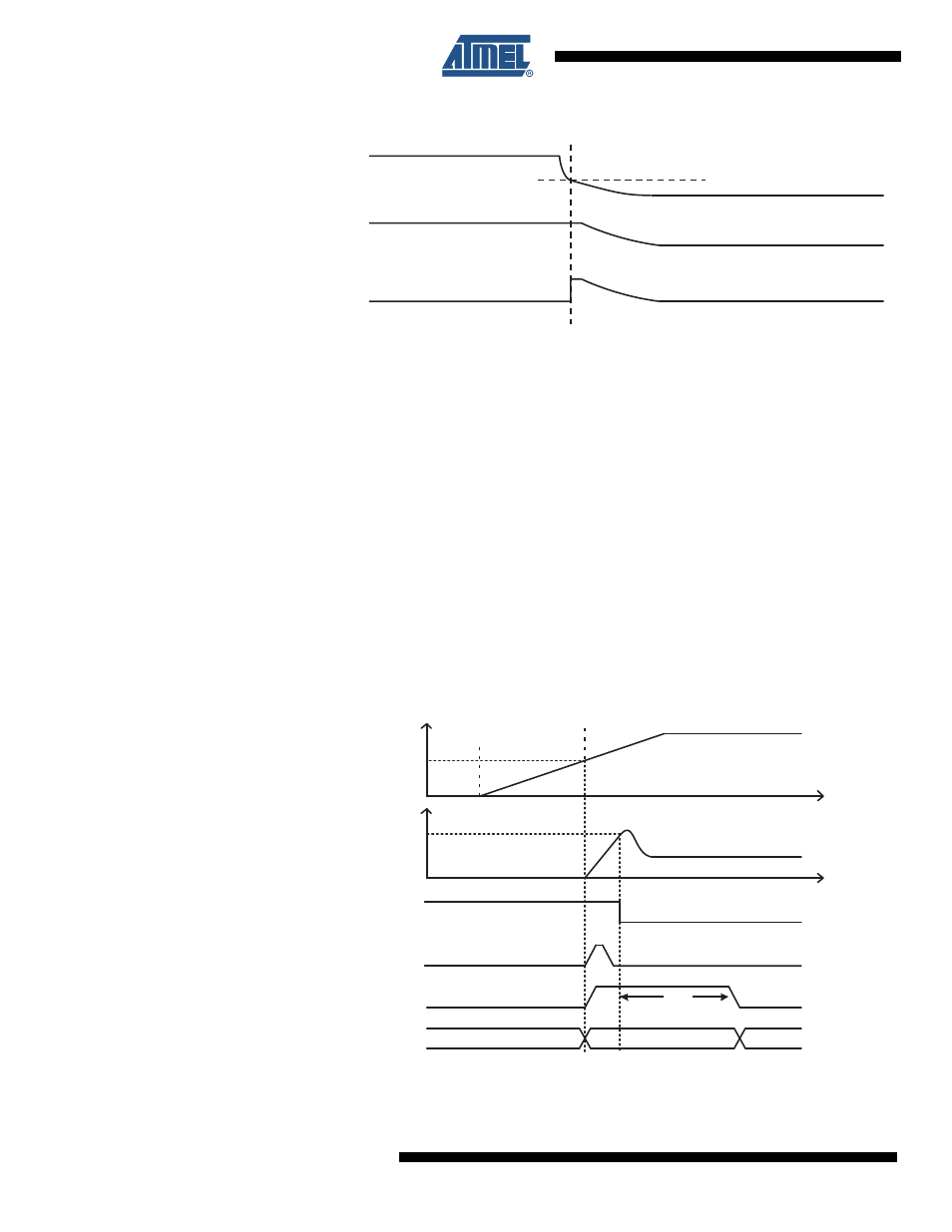
Figure 10-7. Black-out Reset with high current consumption at V
REG
10.6
ATmega4HVD/8HVD Start-up Sequence
The Voltage Regulator will not start until it is enabled by the Charger Detect module. Before
this happens the chip will be in Power-off mode and only the Charger Detect module is
enabled. In order for the Charger Detect module to enable the Voltage Regulator, the V
BATT
voltage must exceed the Power-On Threshold, V
POT
. When the voltage at V
BATT
exceeds V
POT
,
the Voltage Regulator starts up and a Power-On Reset forces the chip into RESET state.
10.6.1
Start-up with one FET connected
During start-up with only one FET (D-FET), cell charging through the body diode of the Dis-
charge FET will start immediately when a charger is connected, even if the chip has not
started yet. The voltage on the BATT pin equals the cell voltage (VFET) plus a diode drop dur-
ing the complete start-up sequence, and will hence increase as the cell is being charged.
A typical start-up sequence for the application is illustrated in
Figure 10-8 on page 42
.
Figure 10-8. Powering up ATmega4HVD/8HVD (1-FET example)
When V
BATT
reaches the power-on threshold V
POT
, the voltage regulator starts up. This causes
VCC to increase rapidly while CREG is being charged. At the same time the digital part of the
V
REG
Power-on
Internal Reset
V
BLOT
Power-off
CHIP STATE
POR
V
BATT
INTERNAL_RESET
t
TOUT
Reset
Active
V
POT
V
REG
2.2 V
V
BLOT, START-UP
BLOD
CHARGER CONNECTED
CHARGER DETECTED