5 modes of operation, Atmega4hvd/8hvd – Rainbow Electronics ATmega8HVD User Manual
Page 76
76
8052B–AVR–09/08
ATmega4HVD/8HVD
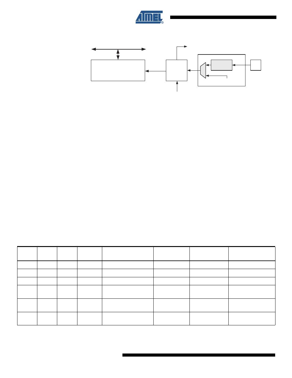
Figure 16-2. Counter Unit Block Diagram
Signal description (internal signals):
count
Increment or decrement TCNTn by 1.
clk
Tn
Timer/Counter clock, referred to as clk
Tn
in the following.
top
Signalize that TCNTn has reached maximum value.
The counter is incremented at each timer clock (clk
Tn
) until it passes its TOP value and then
restarts from BOTTOM. The counting sequence is determined by the setting of the WGMn0
bits located in the Timer/Counter Control Register (TCCRnA). For more details about counting
sequences, see
”Timer/Counter Timing Diagrams” on page 81
. clk
Tn
can be generated from an
external or internal clock source, selected by the Clock Select bits (CSn2:0). When no clock
source is selected (CSn2:0 = 0) the timer is stopped. However, the TCNTn value can be
accessed by the CPU, regardless of whether clk
Tn
is present or not. A CPU write overrides
(has priority over) all counter clear or count operations. The Timer/Counter Overflow Flag
(TOVn) is set when the counter reaches the maximum value and it can be used for generating
a CPU interrupt.
16.5
Modes of Operation
The mode of operation is defined by the Timer/Counter Width (TCWn), Input Capture Enable
(ICENn) and the Waveform Generation Mode (WGMn0)bits in
Control Register A” on page 86
.
Table 16-2 on page 76
shows the different Modes of
Operation.
DATA BUS
TCNTn
Control Logic
count
TOVn
(Int.Req.)
Clock Select
top
Tn
Edge
Detector
( From Prescaler )
clk
Tn
Table 16-2.
Modes of Operation
Mode
ICENn
TCWn
WGMn0
Timer/Counter Mode
of Operation
TOP
Update of
OCRx at
TOV Flag
Set on
0
0
0
0
Normal 8-bit Mode
0xFF
Immediate
MAX (0xFF)
1
0
0
1
8-bit CTC
OCRnA
Immediate
MAX (0xFF)
2
0
1
0
16-bit Mode
0xFFFF
Immediate
MAX (0xFFFF)
3
0
1
1
16-bit CTC
OCRnB,
OCRnA
Immediate
MAX (0xFFFF)
4
1
0
0
8-bit Input Capture
mode
0xFF
–
MAX (0xFF)
5
1
1
0
16-bit Input Capture
mode
0xFFFF
–
MAX (0xFFFF)