Atmega4hvd/8hvd – Rainbow Electronics ATmega8HVD User Manual
Page 111
111
8052B–AVR–09/08
ATmega4HVD/8HVD
Notes:
1. The actual value depends on the actual frequency of the
”Ultra Low Power RC Oscillator” on
”Electrical Characteristics” on page 142
2. Initial value.
3. An additional delay up to T
d
can be expected after enabling the corresponding FET. This is
related to the initialization of the protection circuitry. For the Discharge Over-Current protec-
tion, this applies when enabling the Discharge FET. For Charge Over-Current protection,
this applies when enabling the Charge FET. With nominal ULP frequency this delay is maxi-
mum 0.2 ms.
Note:
Due to synchronization of parameters between clock domains, a guard time of 3 ULP oscillator
cycles + 3 CPU clock cycles is required between each time the BPOCTR register is written. Any
writing to the BPOCTR register during this period will be ignored.
20.8.5
BPSCD – Battery Protection Short-circuit Detection Level Register
• Bits 7:0 – SCDL7:0: Short-circuit Detection Level
These bits sets the R
SENSE
voltage level for detection of Short-circuit in the discharge direction,
as defined in
Table 20-4 on page 112
. This register should always be written as one-hot.
Note:
Due to synchronization of parameters between clock domains, a guard time of 3 ULP oscillator
cycles + 3 CPU clock cycles is required between each time the BPSCD register is written. Any
writing to the BPSCD register during this period will be ignored.
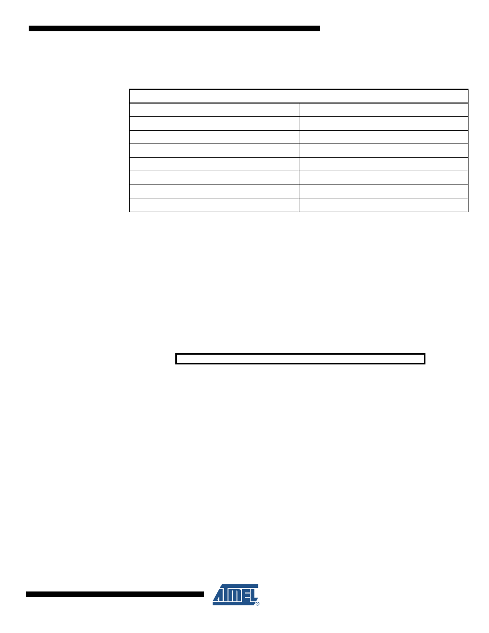
Table 20-3.
Over-current Protection Reaction Time. OCPT[5:0] with corresponding Over-
current Delay Time.
Over-current Protection Reaction Time
(1)
OCPT[5:0]
Typ
0x00
(0.0 - 0.5 ms) + T
d
(3)
0x01
(0.0 - 0.5 ms) + T
d
(3)
0x02
(2)
(0.5 - 1.0 ms) + T
d
(3)
0x03
(1.0 - 1.5 ms) + T
d
(3)
...
...
0x3E
(30.5 - 31.0 ms) + T
d
(3)
0x3F
(31.0 - 31.5 ms) + T
d
(3)
Bit
7
6
5
4
3
2
1
0
SCDL[7:0]
BPSCD
Read/Write
R/W
R/W
R/W
R/W
R/W
R/W
R/W
R/W
Initial Value
0
0
0
0
0
0
0
1