Memory programming, 1 program and data memory lock bits, 2 fuse bits – Rainbow Electronics ATmega8HVD User Manual
Page 129: 1 high byte, Cont, Atmega4hvd/8hvd
129
8052B–AVR–09/08
ATmega4HVD/8HVD
24. Memory Programming
24.1
Program And Data Memory Lock Bits
The ATmega4HVD/8HVD provides two Lock bits which can be left unprogrammed (“1”) or can
be programmed (“0”) to obtain the additional features listed in
Table 24-2
. The Lock bits can
only be erased to “1” with the Chip Erase command.
Note:
1. “1” means unprogrammed, “0” means programmed
Notes:
1. Program the Fuse bits and Boot Lock bits before programming the LB1 and LB2.
2. “1” means unprogrammed, “0” means programmed
24.2
Fuse Bits
The ATmega4HVD/8HVD has two Fuse bytes.
Table 24-4
and
Table 24-3
describe briefly the
functionality of all the fuses and how they are mapped into the Fuse byte. Note that the fuses
are read as logical zero, “0”, if they are programmed.
24.2.1
High Byte
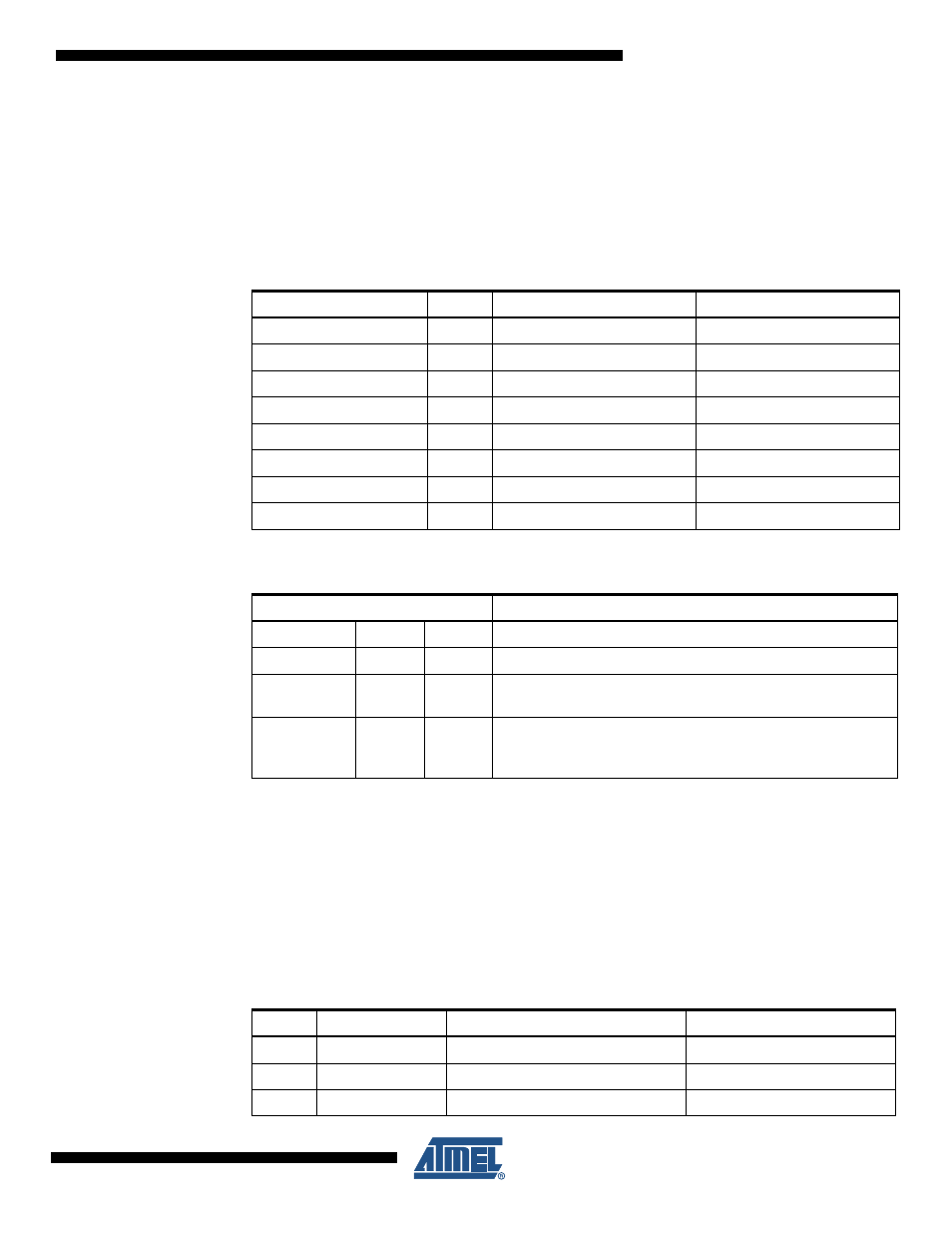
Table 24-1.
Lock Bit Byte
(1)
Lock Bit Byte
Bit No
Description
Default Value
7
–
1 (unprogrammed)
6
–
1 (unprogrammed)
5
–
1 (unprogrammed)
4
–
1 (unprogrammed)
3
–
1 (unprogrammed)
2
–
1 (unprogrammed)
LB2
1
Lock bit
1 (unprogrammed)
LB1
0
Lock bit
1 (unprogrammed)
Table 24-2.
Lock Bit Protection Modes
(1)(2)
Memory Lock Bits
Protection Type
LB Mode
LB2
LB1
1
1
1
No memory lock features enabled.
2
1
0
The Fuse bits are locked and further programming of the Flash
and EEPROM is disabled programming mode.
(1)
3
0
0
The Fuse bits are locked and further programming and
verification of the Flash and EEPROM is disabled
programming mode.
(1)
Table 24-3.
Fuse High Byte
Bit No
Fuse High Byte
Description
Default Value
7:2
–
–
1 (unprogrammed)
1
OSCSEL1
Oscillator Select 1
1 (unprogrammed)
0
OSCSEL0
Oscillator Select 0
0 (programmed)