Atmega4hvd/8hvd – Rainbow Electronics ATmega8HVD User Manual
Page 41
41
8052B–AVR–09/08
ATmega4HVD/8HVD
guaranteed and the chip should be forced into Power-off mode. The algorithm used for switch-
ing between the two V
BLOT
levels is illustrated
Figure 10-4 on page 41
. As long as BLOD is set,
the V
BLOT, START-UP
level will always be selected.
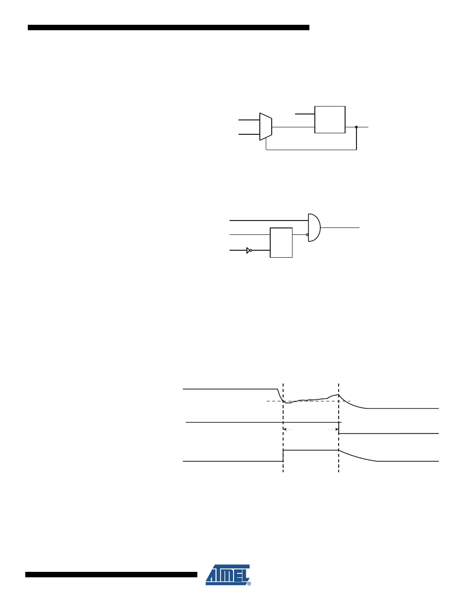
Figure 10-4. BLOD levels switching
Notice that during the Power-On Reset start-up sequence, a Black-out detection will only gen-
erate a normal reset. The chip will not enter Power-off in this case. This is illustrated in
Figure
10-5 on page 41
. See TBD for details on Power-on Reset and start-up sequence.
Figure 10-5. BLOD detection with POR
In normal operation, when V
REG
decreases to a value below the trigger level, the Black-out
Reset is immediately activated. After a fixed delay of T
BLODTOUT
the chip will enter Power-off
mode, see
Figure 10-6 on page 41
and
”System and Reset Characteristics” on page 144
. Any
ongoing operations, including EEPROM write sequences that were started while V
REG
was
above V
BLOD
, will be aborted. The result of an ongoing EEPROM write operation will be invalid.
A charger must be connected to start up the chip from Power-off.
The BLOD circuit will only detect a drop in V
REG
if the voltage stays below the trigger level for
longer than t
BLOD
given in
”System and Reset Characteristics” on page 144
.
Figure 10-6. Black-out Reset During Operation
BLOD
0
1
V
BLOT, NORMAL
V
BLOT,STARTUP
BLOD
DETECTION
BLOD LEVEL
VREG
BLOD_PWROFF
S
R
BLOD
POR
reset
V
CC
Power-on
Internal Reset
V
BLOT
TBLODTOUT