6312khz synchronization interface, Eceive, Ynchronization – Rainbow Electronics DS26503 User Manual
Page 97: Nterface, Peration, Ransmit
DS26503 T1/E1/J1 BITS Element
97 of 123
15. 6312kHz SYNCHRONIZATION INTERFACE
The DS26503 has a 6312kHz Synchronization Interface mode of operation that conforms with Appendix
II.2 of G.703, with the exception that the DS26503 transmits a square wave as opposed to the sine wave
that is defined in the G.703 specification.
15.1 Receive 6312kHz Synchronization Interface Operation
On the receive interface, a 6312kHz sine wave is accepted conforming to the input port requirements of
G.703 Appendix II. Alternatively, a 6312kHz square wave will also be accepted. A 6312kHz square wave
is output on RCLK in the receive direction. RS is not driven in this mode and will be tri-stated.
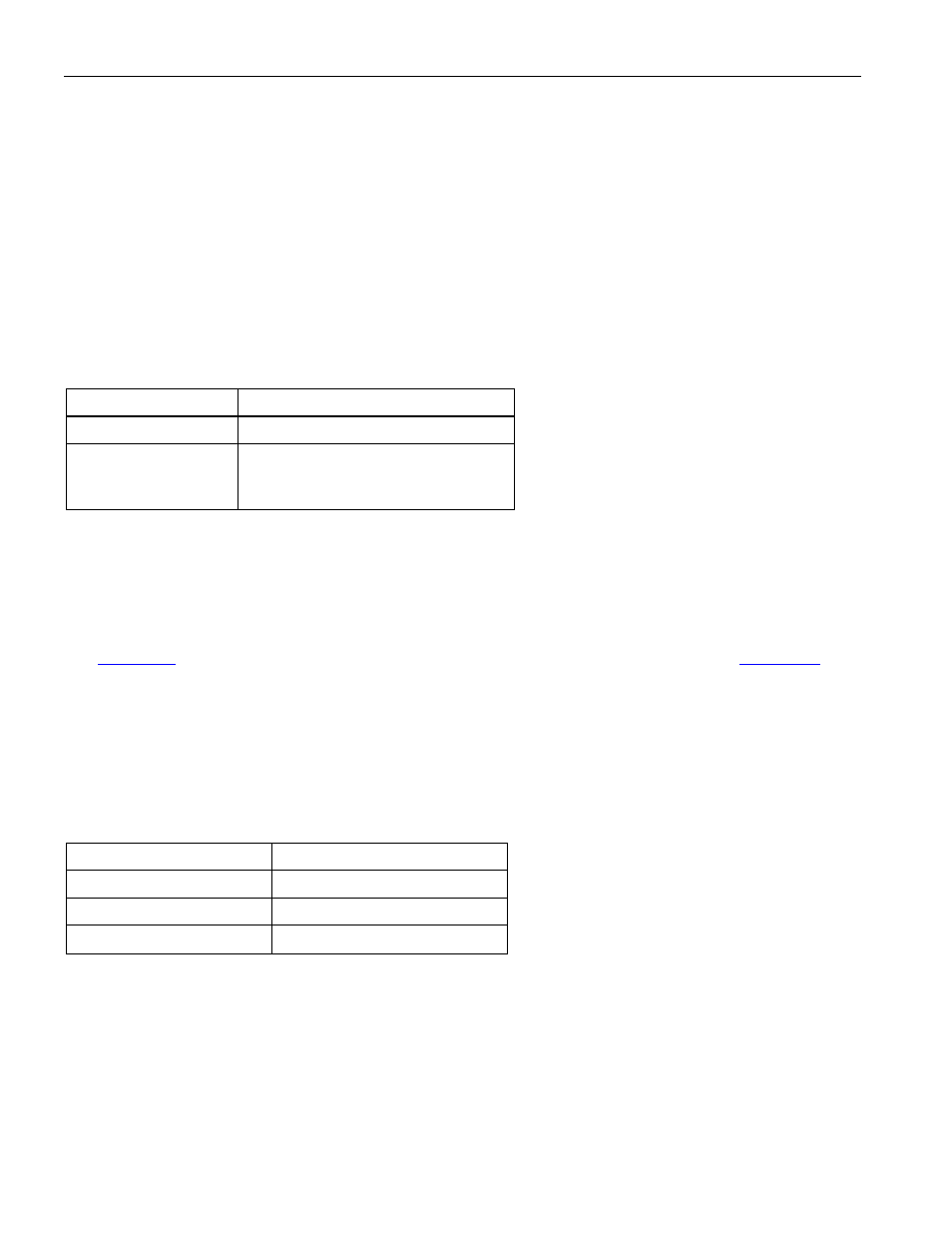
Table 15-1. Specification of 6312kHz Clock
Signal at Input Port
Frequency 6312kHz
Signal format
Sinusoidal wave
Alarm condition
Alarm should not be occurred against
the amplitude ranged
-16dBm to +3dBm
15.2 Transmit 6312kHz Synchronization Interface Operation
On the transmit interface, a nominally 50% duty cycle, 6312kHz square wave at standard logic levels is
available from the PLL_OUT pin. In normal operation, the TCLKO pin will output the same signal.
However, if remote loopback is enabled then TCLKO will be replaced with the recovered receive clock.
See
. The G.703 requirements for the 6312kHz transmitted signal are shown in
user must provide an external circuit to convert the TCLKO or PLL_OUT signal to the level and
impedance required by G.703. The RSER and TS pins are ignored in this mode. TTIP and TRING will
be tri-stated in this mode.
Table 15-2. Specification of 6312kHz Clock
Signal at Output Port
Frequency 6312kHz
Load impedance
75
W resistive
Transmission media
Coaxial pair cable
Amplitude
0dBm
± 3dBm