Pin function description, Transmit pll, Transmit side – Rainbow Electronics DS26503 User Manual
Page 15: Ransmit
DS26503 T1/E1/J1 BITS Element
15 of 123
4.
PIN FUNCTION DESCRIPTION
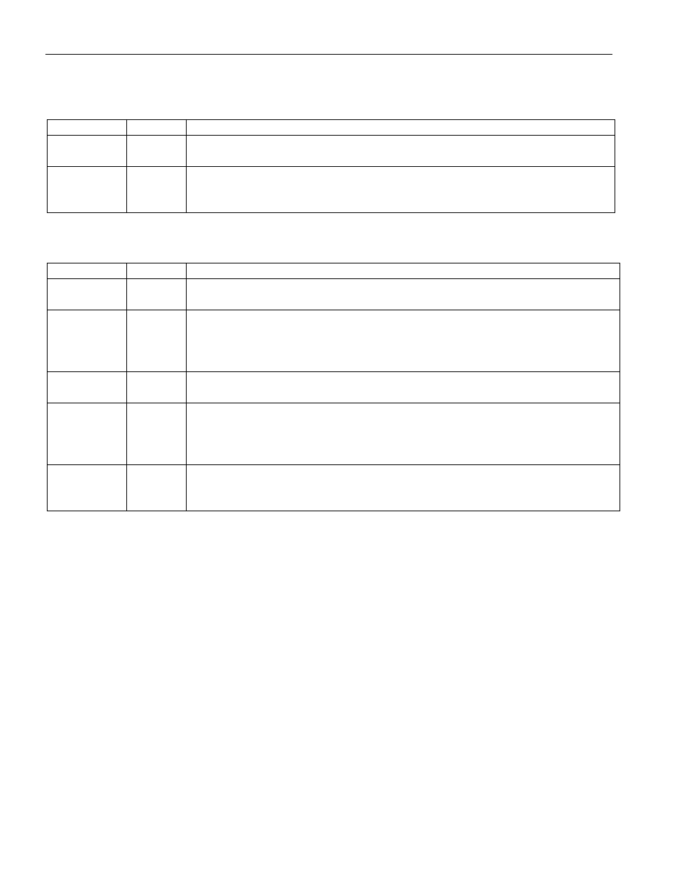
4.1 Transmit PLL
NAME TYPE
FUNCTION
PLL_OUT O
Transmit PLL Output. 1544kHz, 2048kHz, 64kHz, or 6312kHz output from
the internal TX PLL.
TCLK I
Transmit Clock Input. A 64kHz, 1.544MHz, 2.048MHz, or 6312kHz
primary clock. May be selected by the TX PLL mux to provide a clock to the
transmit section.
4.2 Transmit Side
NAME TYPE
FUNCTION
TSER I
Transmit Serial Data. Source of transmit data sampled on the falling edge of
the selected transmit clock.
TS I/O
TSYNC. When in “input” mode, a pulse at this pin will establish either frame
or multiframe boundaries for the transmit side. In output mode, the pin can be
programmed to output a frame or multiframe sync pulse useful for aligning
data.
TCLKO O
Transmit Clock Output. Buffered clock that is used to clock data through the
transmit-side formatter (i.e., either TCLK or RCLK).
TPOSO O
Transmit Positive-Data Output. In T1 or E1 mode, updated on the rising
edge of TCLKO with the bipolar data out of the transmit-side formatter. Can
be programmed to source NRZ data via the output-data format (IOCR1.0)
control bit. In 6312 mode, this pin is low.
TNEGO O
Transmit Negative-Data Output. In T1 or E1 mode, updated on the rising
edge of TCLKO with the bipolar data out of the transmit-side formatter. In
6312 mode, this pin is low.