Loopback configuration – Rainbow Electronics DS26503 User Manual
Page 96
DS26503 T1/E1/J1 BITS Element
96 of 123
14. LOOPBACK CONFIGURATION
Register Name:
LBCR
Register Description:
Loopback Control Register
Register Address:
20h
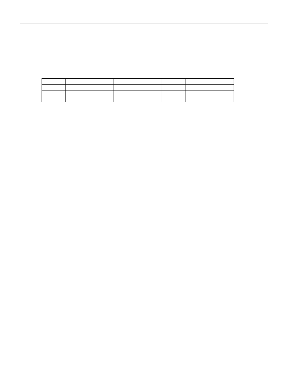
Bit
# 7 6 5 4 3 2 1 0
Name — — — — LLB
RLB — —
Default
0 0 0 0 0 0 0 0
HW
Mode
0 0 0 0 0
RLB
PIN 60
0 0
Bit 0/Unused, must be set = 0 for proper operation.
Bit 1/Unused, must be set = 0 for proper operation.
Bit 2/ Remote Loopback (RLB). In this loopback, data received at RTIP and RRING will be looped back to the transmit LIU.
Received data will continue to pass through the receive side framer of the DS26503 as it would normally and the data from the
transmit side formatter will be ignored.
0 = loopback disabled
1 = loopback enabled
Bit 3/Local Loopback (LLB). In this loopback, data will continue to be transmitted as normal through the transmit side of the
DS26503. Data being received at RTIP and RRING will be replaced with the data being transmitted. Data in this loopback will
pass through the jitter attenuator if enabled.
0 = loopback disabled
1 = loopback enabled
Bit 4/Unused, must be set = 0 for proper operation.
Bit 5/Unused, must be set = 0 for proper operation.
Bit 6/Unused, must be set = 0 for proper operation.
Bit 7/Unused, must be set = 0 for proper operation.