Rainbow Electronics DS26503 User Manual
Page 57
DS26503 T1/E1/J1 BITS Element
57 of 123
Register Name:
BOCC
Register Description:
BOC Control Register
Register Address:
1Fh
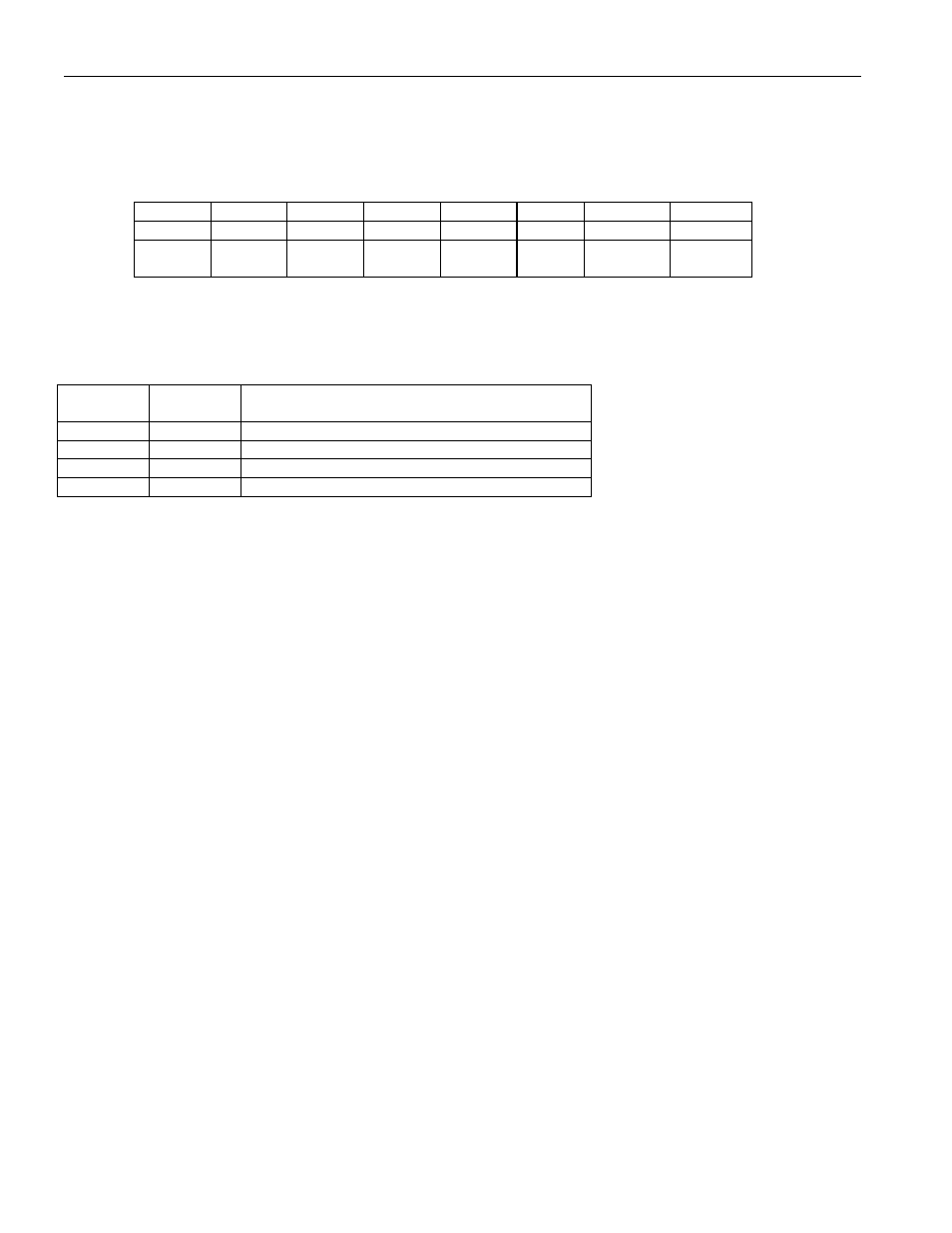
Bit
# 7 6 5 4 3 2 1 0
Name — — —
RBOCE
RBR
RBF1
RBF0
SBOC
Default
0 0 0 0 0 0 0 0
HW
Mode
0 0 0 0 0 0 0 0
Bit 0/Send BOC (SBOC). Set = 1 to transmit the BOC code placed in bits 0 to 5 of the TFDL register.
Bits 1-2/Receive BOC Filter Bits (RBF0, RBF1). The BOC filter sets the number of consecutive patterns that must be
received without error prior to an indication of a valid message.
RBF1 RBF0
CONSECUTIVE BOC CODES FOR VALID
SEQUENCE IDENTIFICATION
0 0
None
0 1
3
1 0
5
1 1
7
Bit 3/Receive BOC Reset (RBR). A 0-to-1 transition will reset the BOC circuitry. Must be cleared and set again for a
subsequent reset.
Bit 4/Receive BOC Enable (RBOCE). Enables the receive BOC function. The RFDL register will report the received BOC
code.
0 = receive BOC function disabled
1 = receive BOC function enabled. The RFDL register will report BOC messages
Bit 5/Unused, must be set = 0 for proper operation.
Bit 6/Unused, must be set = 0 for proper operation.
Bit 7/Unused, must be set = 0 for proper operation.