Test registers, Boundary scan register, Bypass register – Rainbow Electronics DS26503 User Manual
Page 103: Identification register, Egisters, Oundary, Egister, Ypass, Dentification, Table 16-2. id code structure
DS26503 T1/E1/J1 BITS Element
103 of 123
IDCODE
When the IDCODE instruction is latched into the parallel instruction register, the identification test
register is selected. The device identification code will be loaded into the identification register on the
rising edge of JTCLK following entry into the capture-DR state. Shift-DR can be used to shift the
identification code out serially via JTDO. During test-logic-reset, the identification code is forced into the
instruction register’s parallel output. The ID code will always have a 1 in the LSB position. The next 11
bits identify the manufacturer’s JEDEC number and number of continuation bytes followed by 16 bits for
the device and 4 bits for the version
lists the device ID codes.
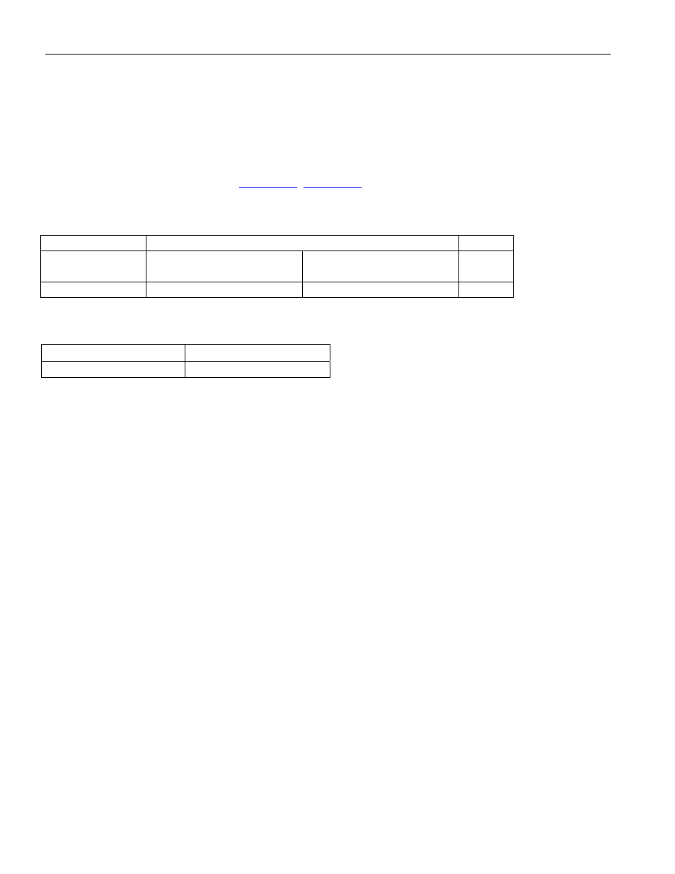
Table 16-2. ID Code Structure
MSB
LSB
Version
Contact Factory
Device ID
JEDEC
1
4 bits
16 bits
00010100001
1
Table 16-3. Device ID Codes
DEVICE 16-BIT
ID
DS26503 0035h
16.2 Test Registers
IEEE 1149.1 requires a minimum of two test registers: the bypass register and the boundary scan register.
An optional test register has been included with the DS26503 design. This test register is the
identification register and is used with the IDCODE instruction and the test-logic-reset state of the TAP
controller.
16.3 Boundary Scan Register
This register contains both a shift register path and a latched parallel output for all control cells and
digital I/O cells and is n bits in length. See for all the cell bit locations and definitions.
16.4 Bypass Register
This is a single 1-bit shift register used with the BYPASS, CLAMP, and HIGHZ instructions that
provides a short path between JTDI and JTDO.
16.5 Identification Register
The identification register contains a 32-bit shift register and a 32-bit latched parallel output. This register
is selected during the IDCODE instruction and when the TAP controller is in the test-logic-reset state.