Rainbow Electronics DS26503 User Manual
Page 25
DS26503 T1/E1/J1 BITS Element
25 of 123
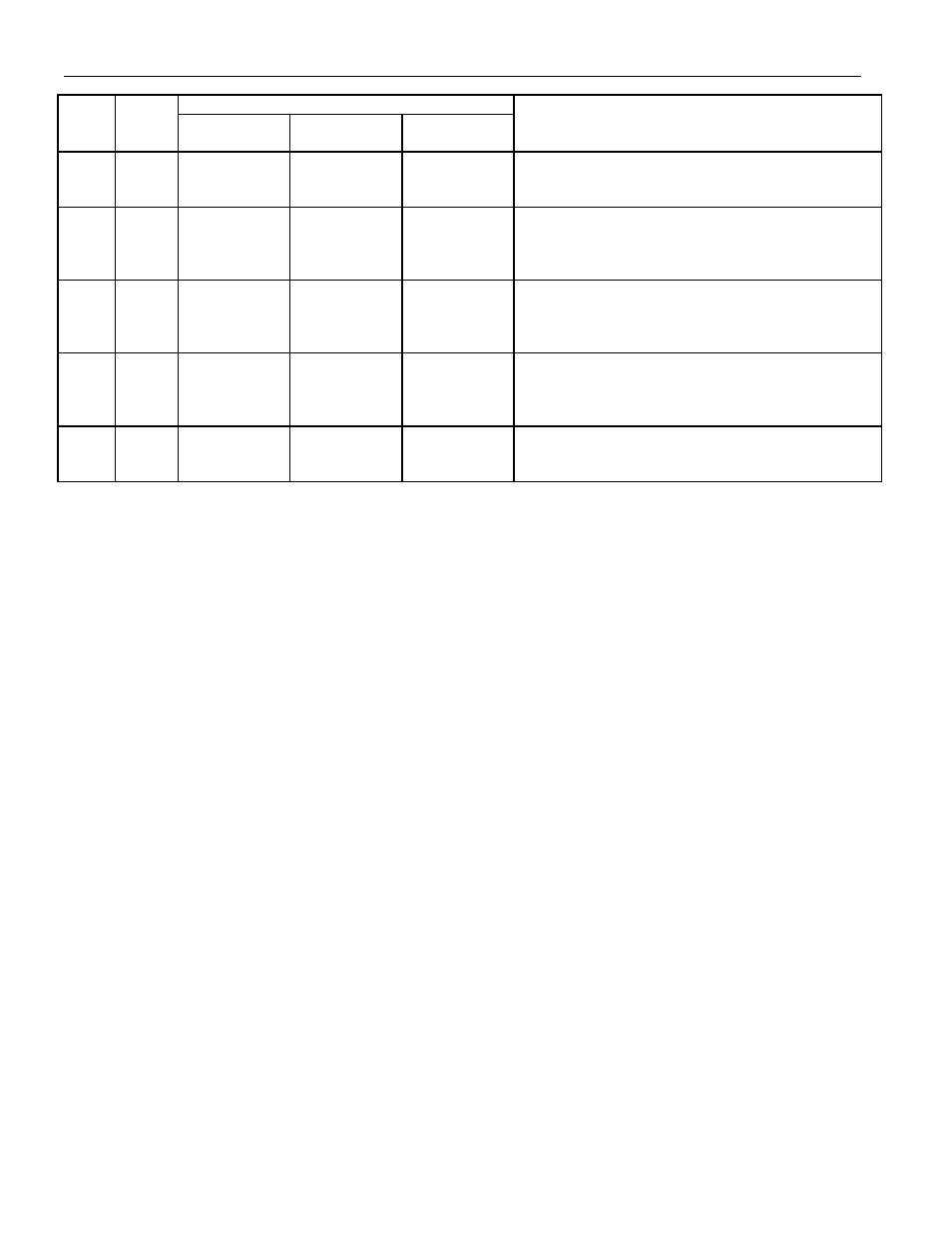
MODE
PIN TYPE PARALLEL
PORT
SERIAL
PORT
HARDWARE
FUNCTION
60 I
CS CS RLB
Parallel Port Mode: Chip Select (Active Low)
Serial Port Mode: Chip Select (Active Low)
Hardware Mode: Remote Loopback Enable
61 I
RD (DS) — RMODE2
Parallel Port Mode: Read Input (Data Strobe), Active
Low.
Serial Port Mode: Unused, should be connected to V
SS
.
Hardware Mode: Receive Mode Select 2
62 I
WR (R/W) — TMODE3
Parallel Port Mode: Write Input (Read/Write), Active
Low
Serial Port Mode: Unused, should be connected to V
SS
.
Hardware Mode: Transmit Mode Select 3
63 I/O
AD0
MIS0
TCSS0
Parallel Port Mode: Address/Data Bus Bit 0
Serial Port Mode: Serial Data Out (Master In-Slave
Out)
Hardware Mode: Transmit Clock Source Select 0
64 I/O
AD1
MOSI
RMODE3
Parallel Port Mode: Address/Data Bus Bit 1
Serial Port Mode: Serial Data In (Master Out-Slave In)
Hardware Mode: Receive Mode Select 3
- MAX12005 (14 pages)
- MAX7058 (14 pages)
- MAX9995 (13 pages)
- MAX7034 (13 pages)
- MAX7033 (16 pages)
- MAX9476 (8 pages)
- MAX9486 (8 pages)
- MAX14821 (29 pages)
- MAX9489 (11 pages)
- MAX9491 (11 pages)
- DS2130Q (22 pages)
- DS21458 (270 pages)
- DS3131 (174 pages)
- DS26502 (125 pages)
- DS2153Q (48 pages)
- DS2186 (11 pages)
- DS1842A (6 pages)
- DS3134 (203 pages)
- DS1876 (69 pages)
- DS1874 (88 pages)
- DS31256 (181 pages)
- DS2141A (35 pages)
- DS3184 (13 pages)
- DS2154 (69 pages)
- DS26504 (128 pages)
- DS3164 (12 pages)
- DS1852 (25 pages)
- DS2181A (32 pages)
- DS2151Q (46 pages)
- DS1843 (8 pages)
- DS2165Q (17 pages)
- DS3170 (233 pages)
- DS2180A (36 pages)
- DS2172 (20 pages)
- DS2152 (79 pages)
- DS1841 (16 pages)
- DS2182A (22 pages)
- DS2143Q (40 pages)
- DS2132A_Q (17 pages)
- DS1862 (42 pages)
- DS26519 (310 pages)
- DS2188 (11 pages)
- DS1875 (92 pages)
- DS33M33 (20 pages)