Cmi (code mark inversion) option, Cmi (c, Nversion – Rainbow Electronics DS26503 User Manual
Page 81: Ption, Figure 13-3. cmi coding, 6 cmi (code mark inversion) option
DS26503 T1/E1/J1 BITS Element
81 of 123
15 or 17 instead of the normal 16 to keep the buffer from overflowing. When the device divides by either
15 or 17, it also sets the Jitter Attenuator Limit Trip (JALT) bit in Status Register 1 (SR1.4).
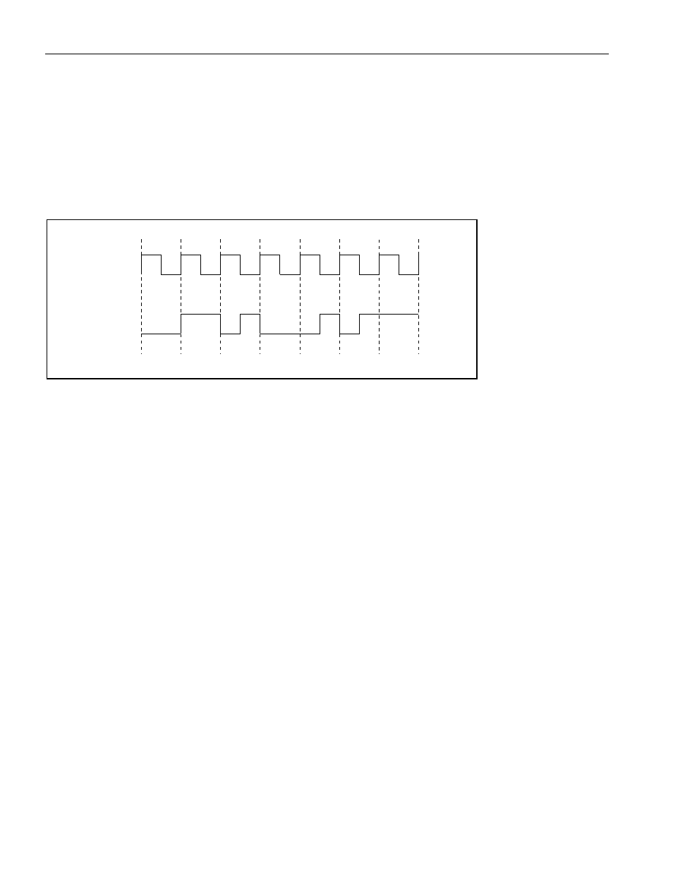
13.6 CMI (Code Mark Inversion) Option
The DS26503 provides a CMI interface for connection to optical transports. This interface is a unipolar
1T2B type of signal. Ones are encoded as either a logical one or zero level for the full duration of the
clock period. Zeros are encoded as a zero-to-one transition at the middle of the clock period.
Figure 13-3. CMI Coding
Transmit and receive CMI is enabled via LIC4.7. When this register bit is set, the TTIP pin will output
CMI-coded data at normal levels. This signal can be used to directly drive an optical interface. When
CMI is enabled, the user can also use HDB3/B8ZS coding. When this register bit is set, the RTIP pin will
become a unipolar CMI input. The CMI signal will be processed to extract and align the clock with data.
0
1
1
1
0
0
1
CLOCK
DATA
CMI