Rainbow Electronics DS26503 User Manual
Page 51
DS26503 T1/E1/J1 BITS Element
51 of 123
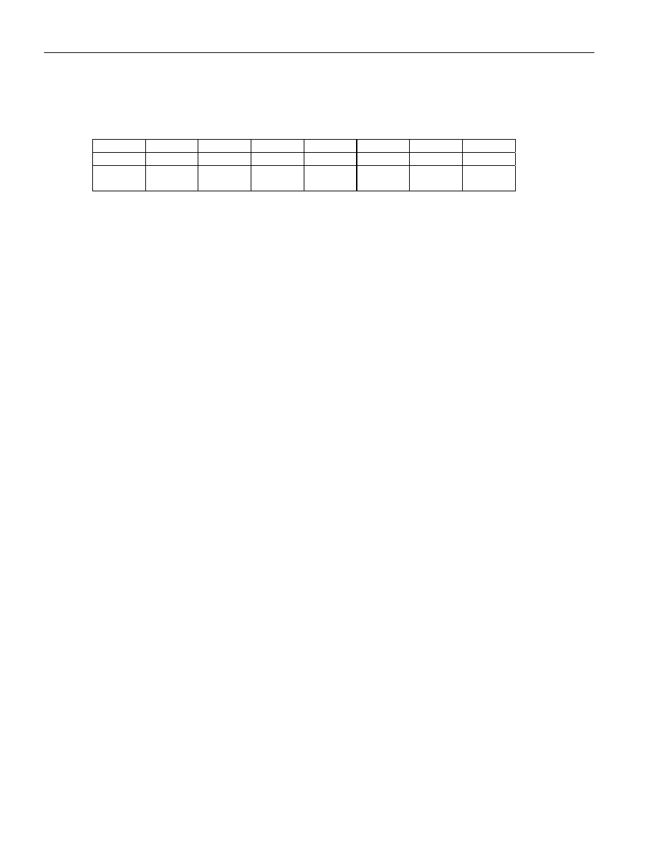
Register Name:
IMR2
Register Description:
Interrupt Mask Register 2
Register Address:
17h
Bit
# 7 6 5 4 3 2 1 0
Name RYELC
RAISC
RLOSC
RLOFC
RYEL RAIS RLOS RLOF
Default
0 0 0 0 0 0 0 0
HW
Mode
X X X X X X X X
Bit 0/Receive Loss of Frame Condition (RLOF).
0 = interrupt masked
1 = interrupt enabled–interrupts on rising edge only
Bit 1/Receive Loss Of Signal Condition (RLOS).
0 = interrupt masked
1 = interrupt enabled–interrupts on rising edge only
Bit 2/Receive Alarm Indication Signal Condition (RAIS).
0 = interrupt masked
1 = interrupt enabled–interrupts on rising edge only
Bit 3/Receive Yellow Alarm Condition (RYEL).
0 = interrupt masked
1 = interrupt enabled–interrupts on rising edge only
Bit 4/Receive Loss of Frame Clear Event (RLOFC).
0 = interrupt masked
1 = interrupt enabled
Bit 5/Receive Loss Of Signal Condition Clear (RLOSC).
0 = interrupt masked
1 = interrupt enabled
Bit 6/Receive Alarm Indication Signal Clear Event (RAISC).
0 = interrupt masked
1 = interrupt enabled
Bit 7/Receive Yellow Alarm Clear Event (RYELC).
0 = interrupt masked
1 = interrupt enabled